1
\$\begingroup\$

I`m new to electrical engineering, so it's probably a newbie problem.

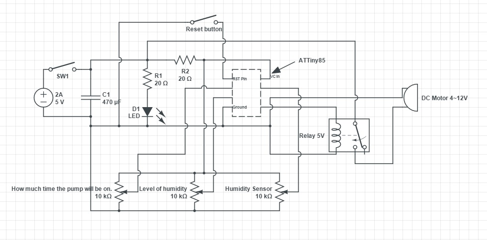
I'm using a wall power supply(5V-2A) to power the DC Motor and the Attiny85.

A C1 470uF to make the power more stable. I don't know if it is necessary, but it helped.

A D1 green led to show if it's on.

A reset button connected to ground to reset(Duh).

One relay(833H-1C-C) connected to the digital pin 0 of the attiny to turn the motor on and off.

Two rotational potentiometer connected to two analog pins(2,3) to decide how much time the mini water pump will be on(0-1023 to 1s-30s) and the other to compare to the humidity sensor to decide how dry the soil will need to be to turn on the motor.

And one humidity sensor.

#include "kPot.h" // my library, just analogReads

#define HUMIDITY_PIN 1 //humidity sensor
#define LEVEL_PIN 3 //rotational potentiometer
#define TIMER_PIN 2 //rotational potentiometer
#define MOTOR_PIN 0 //connected to the relay switch

kPot humiditySensor = kPot(HUMIDITY_PIN, 10); //(pin, average of 10 reads)
kPot levelPot = kPot(LEVEL_PIN, 10);
kPot timerPot = kPot(TIMER_PIN, 10);

int humidity = 0;
int level = 0;
int timer = 0;

void setup() {
  pinMode(MOTOR_PIN, HIGH);  

  humidity = humiditySensor.Read();
  level = levelPot.Read();
  timer = timerPot.Read();
}

void loop() {
  humidity = humiditySensor.Read();
  level = levelPot.Read();

  timer = timerPot.Read();
  timer = map(timer, 0, 1023, 1000, 30000); //1s to 30s


  if(humidity < level){
    digitalWrite(MOTOR_PIN, HIGH);
    delay(timer);
    digitalWrite(MOTOR_PIN, LOW);
  }

  delay(300000); // 5min Update
}

enter image description here

The problem: The mini water pump turns on and won't stop.
I removed the reset button to make sure that wasn't resetting, didn't help.
Maybe the motor is taking too much current and reseting the attiny?
I probably have to put a diode somewhere, but as I said, I'm a newbie, so...

thanks.

\$\endgroup\$
12
  • \$\begingroup\$ Where is the decoupling capacitor? And why is there a resistor on the supply line? \$\endgroup\$ Commented Jan 30, 2016 at 0:27
  • \$\begingroup\$ Is your reset switch designed exactly as drawn? If so you probably need either an internal or external pull-up resistor to keep that input from floating when the reset button isn't pressed. \$\endgroup\$ Commented Jan 30, 2016 at 0:44
  • \$\begingroup\$ @RobhercKV5ROB pull-up is correct. A pull-down would hold it permanently in reset whether the button is pressed or not. \$\endgroup\$
    – brhans
    Commented Jan 30, 2016 at 1:25
  • \$\begingroup\$ Lose the resistor. Don't try to drive the relay directly from your Attiny - use a transistor. Put a diode across the relay coil. \$\endgroup\$
    – brhans
    Commented Jan 30, 2016 at 1:28
  • 1
    \$\begingroup\$ 20ohms is far too small for your LEDs series resistor. You should use one 10 to 20 times higher than that. \$\endgroup\$
    – brhans
    Commented Jan 30, 2016 at 1:31

1 Answer 1

0
\$\begingroup\$

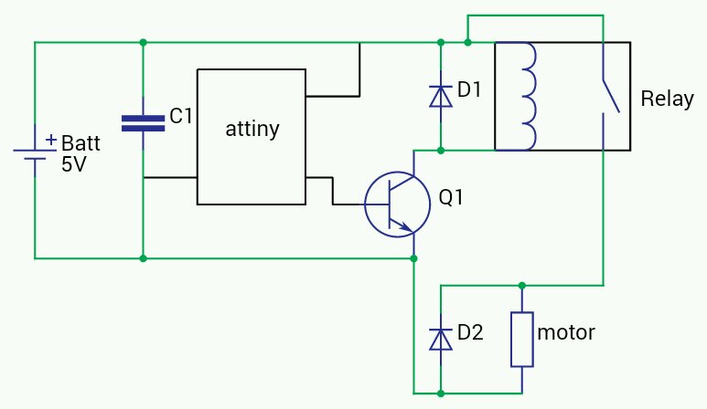
Ok, not sure this will fix everything, but it should at least improve several problems (and avoid some component damage).

Try adding 2 diodes, a transistor, and a decoupling capacitor to your circuit like this:
enter image description here

EDIT: Updated schematic to include decoupling cap.

\$\endgroup\$
4
  • \$\begingroup\$ I'm adding right now the Diodes and transistor. But the decoupling capacitor was already there...C1 on the original schematic. \$\endgroup\$ Commented Jan 30, 2016 at 2:20
  • \$\begingroup\$ ok, but it needs to be on the other side of R2 from your orig. schematic (i.e. attached to the same end of R2 as your ttiny) \$\endgroup\$ Commented Jan 30, 2016 at 2:24
  • \$\begingroup\$ It's working perfectly with the adding of a transistor, diodes, capacitor in this schematic and the pull up resistor on the reset button. Thanks! \$\endgroup\$ Commented Jan 30, 2016 at 2:47
  • \$\begingroup\$ @KaiqueGomes: C1 is bulk, not decoupling. They serve different purposes. \$\endgroup\$ Commented Jan 31, 2016 at 13:09

Your Answer

By clicking “Post Your Answer”, you agree to our terms of service and acknowledge you have read our privacy policy.

Not the answer you're looking for? Browse other questions tagged or ask your own question.