1
\$\begingroup\$

The building I live in have an old door-chime system, and I wish send a wireless signal when the door-chime is triggered.

There are multiple push-buttons at different locations connected to the same circuit. The only place I can access my part of the wiring of the old door-chime system is behind one of the push-buttons, the rest of the system is buried behind concrete and walls. There's an AC transformer hooked up to the system to drive a door bell. The bell has been removed some time in the past, and the wires are not accessible - and are probably shorted.

I've measured 8V AC over the button, the button is normally open.

I've a board with a wireless transmitter, it's triggered by pulling an interrupt pin to GND. Powered by a 3v battery.

I want to pull this pin low to trigger the transmitter whenever the doorbell circuit is closed.

My naive idea is something like the following:
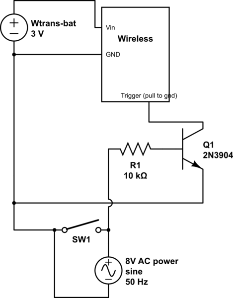
schematic

simulate this circuit – Schematic created using CircuitLab

Will this work? Or will the AC source (which hits the base and emitter of the transistor) ruin this somehow?

\$\endgroup\$
2
  • \$\begingroup\$ Do you think the wiring is shorted where the original bell was? If you put a 12 V car tail-lamp (6W, 0.5 A) across the bell terminals will it light up? \$\endgroup\$
    – Transistor
    Commented Feb 3, 2016 at 22:40
  • \$\begingroup\$ @transistor: I'm afraid I do not know the original bell position, a previous owner moved several of the walls, and bell/wiring was lost in the process. I do not know if they are shorted accidentally or intentionally - but I read ~8V AC over all of the buttons' terminals. Measuring current with a multimeter and a resistor over the button terminals is a good test, I'll try that tomorrow. \$\endgroup\$
    – Pie-rat
    Commented Feb 3, 2016 at 23:10

3 Answers 3

1
\$\begingroup\$

schematic

simulate this circuit – Schematic created using CircuitLab

Figure 1. What you've probably got.

There's something strange about your setup. If there is a short where the bell was (LO-Z in Figure 1) then there is a danger of the transformer overheating if the button is held in or fails short-circuit. If the bell had simply been removed there would be two breaks in the circuit and you wouldn't detect voltage on the switch - unless it's a high impedance meter picking up strays. As per my comment, see if there is enough current to light a 6 W, 0.5 A car tail lamp.

schematic

simulate this circuit

Figure 2. AC-less solution.

Since you don't seem to mind using a battery, the AC is no advantage. It can be disconnected and the house made a little safer. You'll need to figure out which button has the supply.

If you purchase a remote control coded key-fob or a standard wireless doorbell system you should be able to solder some wires onto the push button pads or leads. Extend these out and hook up to the parallel switches. I really don't know if the long house wiring will affect the input so some testing may be required. A small capacitor - 100 nF? - across the original fob button may do the trick.

\$\endgroup\$
2
  • \$\begingroup\$ Good advice, will try to measure current across switch tomorrow and report back. Also try to track down the transformer. I suspect it's inside a wall, but hopefully reachable from behind one of the buttons \$\endgroup\$
    – Pie-rat
    Commented Feb 3, 2016 at 23:26
  • \$\begingroup\$ Frequently I've found doorbell transformers stashed im pseudorandom locations in attics, usually plugged into an outlet up there that serves no other purpose. (hope that helps with your xfmr hunt) \$\endgroup\$ Commented Feb 4, 2016 at 2:07
0
\$\begingroup\$

With the ac voltage being higher than your circuit voltage, it could easily end up damaging your components.

In order to avoid this damage, you pretty much have 3 choices:

  1. Disconnect the ac power, then simply wire the switch directly to your circuit.
  2. Purchase a relay that can be triggered by 8VAC, wire the relay to the AC power & the switch, then have the relay activate your circuit.
  3. Build a bridge rectifier & a voltage divider (and mayne a comparator, if you end up having trouble), so you can "filter down" that 8VAC to something closer to the 3VDC that your circuit can use.
\$\endgroup\$
0
\$\begingroup\$

So, imagine the situation. You have your wireless receiver hooked up to drive a bell in your apartment. What happens next....

Some guy down the street activates his key fob to open his car door and your bell tinkles. Someone in the same apartment switches on their remote controlled lights and your bell tinkles. In fact anyone using the same frequency will activate your bell.

But it's worse than that - any receiver worth its salt will have pretty good sensitivity (in order to maximize range) and the data output pin will be jumping up and down continually - any bit of RF energy in the vicinity of your radio's operating frequency will trigger your receiver and after about 5 minutes you'll disconnect the power and curse radios forever.

You MUST send something intelligible from your transmitter that can be 99.999999999999999% reliable at being uniquely decoded by your receiver as the message you want to hear. This means your transmitter has to: -

  • Send a recognizable preamble of data
  • Send a codeword that you can recognize as likely coming from your transmitter and very few else
  • Send some error checking bits that allows you to verify that it is YOUR transmitter sending the message.

Adding more sophistication to the transmission gives you far fewer instances of an incorrect positive. You need to send data. You need to receive data. You need to decode data. You need to verify that data. You need microprocessors.

\$\endgroup\$
2
  • \$\begingroup\$ Ah, I'm sorry, I simplified the description of the transmitter, since that part of the circuit is working. It's in fact a MCU+radio combo, sends a coded signal and also debounces the input trigger pin. It communicates with my home automation system. \$\endgroup\$
    – Pie-rat
    Commented Feb 3, 2016 at 22:48
  • \$\begingroup\$ -1 for wasting my valuable time. \$\endgroup\$
    – Andy aka
    Commented Feb 3, 2016 at 23:07

Your Answer

By clicking “Post Your Answer”, you agree to our terms of service and acknowledge you have read our privacy policy.

Not the answer you're looking for? Browse other questions tagged or ask your own question.