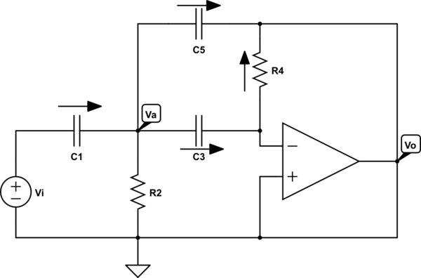
Hey I got an assignment on which I need to calculate the transfer function. It is about the following circuit:

simulate this circuit – Schematic created using CircuitLab
So my approach (note all capicitors values are the same and so referred to as C):
- At node A: i1 = i2 + i3 + i5
Ideal opamp so: i3 = i4 $$\frac{Ua}{Zc}=-\frac{Uo}{R4}$$ $$Ua=-\frac{UoZc}{R4}$$
Filling in 1.: $$\frac{Ui-Ua}{Zc} = \frac{Ua}{R2}+\frac{Uo}{R4}+\frac{Ua-Uo}{Zc}$$
$$\frac{Ui+\frac{UoZc}{R4}}{Zc}=-\frac{\frac{UoZc}{R4}}{R2}-\frac{Uo}{R4}-\frac{\frac{UoZc}{R4}-Uo}{Zc}$$ $$UiZc+\frac{UoZc^2}{R4}=-\frac{UoZcR2}{R4}-\frac{Uo}{R4}-\frac{UoZc^2-UoZcR4}{R4}$$ $$UiZc=\frac{-UoZcR2-Uo-UoZc^2-UoZc^2-UoZcR4}{R4}$$ $$Ui=\frac{-UoZcR2-Uo-UoZc^2-UoZc^2-UoZcR4}{R4Zc}$$ $$\frac{Uo}{Ui}=\frac{R4Zc}{-2Zc^2-ZcR2-ZcR4-1}$$ $$Zc=\frac{1}{jwC}$$
$$\frac{Uo}{Ui}=\frac{jwCR4}{(jwC)(-jwC-R2-R4)-2}$$
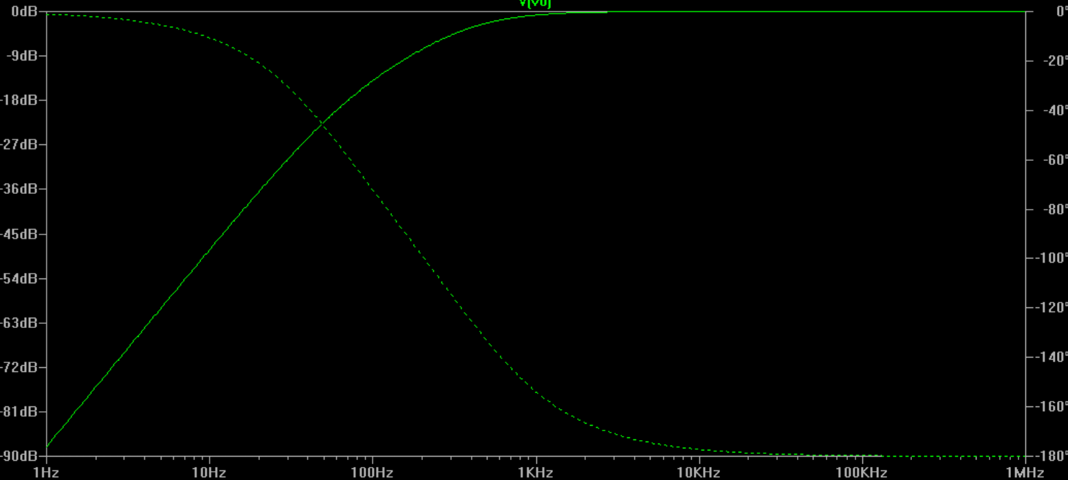
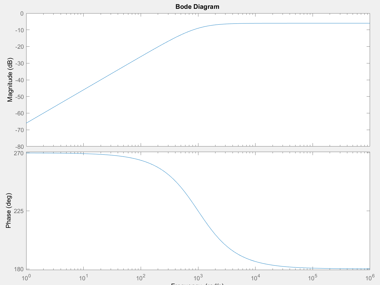
So the question is is this correct? I hope it is however I tried testing my results by simulating the design in LTSpice, taking R4 = R2 = 1K and C = 1uF and then I entered the formula, with the same component values, in matlab however the graphs are not the same.. :(
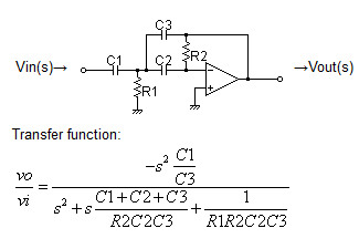
EDIT Okay now it is confirmed the answer is wrong how would I derive such circuit? I tried it again but I'm yet again not getting the right answer.. I won't post it here since it takes to much time to type it out.


