Am building myself a robot chasis that is RC controlled. There is an RC receiver attached in solution and I have a remote RC transmitter. When the motors are not running, I get a perfectly clean signal on the output of my receiver ... a PWM signal. Here is a quick trace when the motors are NOT running:
When I switch on the motors, and then run them up, the signal as measured on the PWM output becomes the following:
If you look closely, you can see the good signal (every 20 msecs) but with lots and lots of noise.
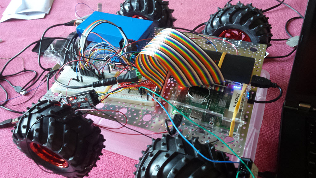
Here is a picture of my robotics chassis:
My scenario was previously working but in this setup, two things have changed:
- I am using a metal sheet for my chassis
- I am using 4 new motors that I previously hadn't used before. They are 170RPM motors as found here:
https://www.servocity.com/html/170_rpm_econ_gearmotor__638354.html
My questions are:
- What is introducing this "noise" when the motors run?
- How can I eliminate the noise?
Unfortunately I'm a "software" guy and mechanical electronics is not my comfort zone but am willing to learn/study.
Looking forward to any assistance.
... later ...
I have a new clue, I placed my digital signal analyzer on an otherwise unused GPIO on the Raspberry Pi and when the motors were not running, the signal was constant flat. However, when I ran the motors, interference was found ... see:
This makes me think that the "setup" is receiving a ton of interference when the motors run ... but I'm at a loss of how to alleviate the problem.
Neil
... later ... after answer proposal from Richard ...
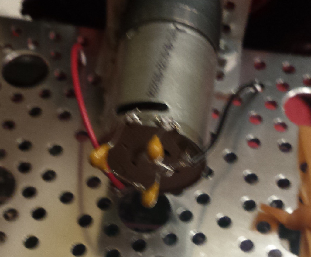
I soldered in 3 capacitors per motor. Each capacitor was 0.1uF. One capacitor across the +/- of the motor and two capacitors from the motor terminals to the casing.
See (sorry about the blur):
I then re-ran the tests and captured a new signal analyzer recording. Sadly, nothing obvious has changed. See:
With no motors running, a perfectly flat line.


