1
\$\begingroup\$

I'm using this depletion-mode MOSFET in a high-voltage power-management circuit. My 500V DC supply isn't high grade, and now that I've blown two of these MOSFETs (gate shorts to drain) I'm wondering if I can put any components on either side to protect it? I was getting weird results with the first one before realizing it was blown. I might have blown the second one (not sure at which point in my testing it failed) simply by turning the high-voltage supply on with it wired like this:

schematic

simulate this circuit – Schematic created using CircuitLab

For protection purposes: If it simplifies things I never want to see more than 200mA through the circuit. If no better ideas I guess I could put a fast-blow fuse in front of V+? But I'm not sure if that's the only thing that can blow this MOSFET. E.g., I'm beginning to wonder if having no load on the drain can cause problems.

\$\endgroup\$
9
  • \$\begingroup\$ What is this schematics? I don't see any reason why this shoudn't blow off. \$\endgroup\$ Commented May 10, 2016 at 18:11
  • 1
    \$\begingroup\$ @MarkoBuršič - Explain why? Lack of load on drain? I couldn't find anything in the specs constraining drain voltage other than to be less than 1000V over source. And the power resistor on source should limit current to 5A even if the MOSFET isn't adding any resistance (which, according to its spec sheet, it should). NB: The MOSFET is heat-sinked. \$\endgroup\$
    – feetwet
    Commented May 10, 2016 at 18:20
  • \$\begingroup\$ Please explain what you want to acheive, maybe I am wrong, but this circuit can just blow your MOSFET and nothing else. Perhaps you will get some information to modify this, if you specify the purpose. \$\endgroup\$ Commented May 10, 2016 at 18:24
  • \$\begingroup\$ Goal is to provide constant current to a varying-resistance load on the drain side. Which it does quite well at low voltage. It also does it at high voltage until something blows the MOSFET. The circuit has to be able to survive an effectively zero-resistance load (i.e., a short) on the drain to V+. If that would be expected to blow the MOSFET I would be interested to know why, but even more interested to know how I can protect and recover the circuit from that condition. \$\endgroup\$
    – feetwet
    Commented May 10, 2016 at 18:38
  • \$\begingroup\$ Few notes: 0.2A*1000 Ohm=200V, A Vgs of -200V is just too much. Second, Vds =500-200=300V, P_dissipating=300*0,2=60W, which is also too much. Not sure about the schematics, if this circuit can really work as constant current source, don't know where you got it. \$\endgroup\$ Commented May 10, 2016 at 18:53

3 Answers 3

9
\$\begingroup\$

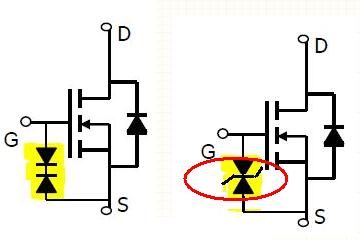
The common way to protect a MOST gate is to use a Zener diode between gate and source. Your MOST has a max Vgs of 20V so add a ~15V zenned diode in reverse bias and you'll be fine. There are also devices called transils, which are specialized for over-voltage protection but do basically the same.

enter image description here

\$\endgroup\$
4
  • \$\begingroup\$ So if the MOST failed with a short between gate and drain then it must have been caused by excessive voltage difference between gate and source? \$\endgroup\$
    – feetwet
    Commented May 10, 2016 at 18:15
  • \$\begingroup\$ If you get a G-D short it will kill the MOST and the Zener diodes with it. Maybe when connecting the transistor the gate caught some static or got charge through capacitive coupling and the voltage blew the gate oxide. Hard to tell what are you trying to do with this circuit, but do try the protection diodes first. They may point you to the source of the problem \$\endgroup\$
    – user68591
    Commented May 10, 2016 at 18:32
  • \$\begingroup\$ I have only observed that the malfunctioning MOSTs have a G-D short. I.e., I take it as evidence that the MOST is blown. But I don't know why or how it happened. I just added clarification of the circuit's purpose in question comment. \$\endgroup\$
    – feetwet
    Commented May 10, 2016 at 18:43
  • \$\begingroup\$ So I want a Zener or TVS to shunt current when Vgs exceeds ~15V. I.e., "clamping" voltage should be under 15V? And, presumably, all other voltage specs for such a diode will be under 15V so any such will do, and in either orientation? Even though this circuit could present a voltage difference in the hundreds of volts? Or is there some other specification I need to watch? \$\endgroup\$
    – feetwet
    Commented May 10, 2016 at 22:08
6
\$\begingroup\$

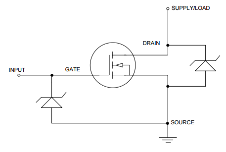
This small Semtech TVS Diode Application Note called "Transient Protection of MOSFETs" provides detailed recommendations on employing TVS diodes to protect both the more sensitive gate and the entire MOSFET against transients, by connecting the diodes like this:

MOSFET Protection circuit

\$\endgroup\$
4
  • \$\begingroup\$ @uhoh – I just updated the link, but the essence of the recommendations are summarized in the circuit diagram. \$\endgroup\$
    – feetwet
    Commented Mar 18, 2018 at 3:22
  • \$\begingroup\$ Link is broken again. \$\endgroup\$ Commented Feb 19, 2022 at 20:43
  • 1
    \$\begingroup\$ @maxschlepzig - Hi, I couldn't find it any longer on the original website. However I found it on Digikey, so I updated the link to point there. \$\endgroup\$
    – SamGibson
    Commented Feb 19, 2022 at 21:51
  • 1
    \$\begingroup\$ @SamGibson thank you. Ok, just in case, for future reference, the linked document's meta data: Semtech, SI96-13, Surging Ideas, TVS Diode Application Note, Revision 9/2000 \$\endgroup\$ Commented Feb 19, 2022 at 21:58
4
\$\begingroup\$

Just wanted to add, for future people viewing this, why the original circuit was failing. If the transistor turns on more than a little then a large portion of the supply voltage is across the resistor, causing Vgs to be a high negative voltage. In ideal conditions this would never happen but was likely occurring due to either pulse effects when turning on, or it began oscillating at some point. This could be avoided with a small capacitor from gate to source and a resistor, if this current limiter does not need to respond very quickly these can be oversized, making the selection easier. And still throw a zener in there just in case.

This circuit should both protect the gate and reduce the chance of oscillation:

schematic

simulate this circuit – Schematic created using CircuitLab

\$\endgroup\$
1
  • 3
    \$\begingroup\$ From my own experience with Zener diodes being used as protection against transients, don't use Zeners rated for less than 1W. I have checked the pulse response of 1/2W Zeners vs. 1W Zeners, and the 1/2W ones let the voltage overshoot happen, while the 1W ones cut it off. (I know it's an old question/answer, but I had to share this for others) \$\endgroup\$ Commented Aug 29, 2020 at 19:52

Your Answer

By clicking “Post Your Answer”, you agree to our terms of service and acknowledge you have read our privacy policy.

Not the answer you're looking for? Browse other questions tagged or ask your own question.