1
\$\begingroup\$

I am designing a simple circuit that will light a LED when a given resistance is between 0 and about 1K. At about 1k the LED would not be lit at all. The test circuit should not have more than .5ma go though the tested resistor. The supply voltage is coming from a car battery so it will vary between 12.5 to about 11 volts.

What I have worked out so far with limited success is to setup a voltage divider between the supply and ground using a 39k resistor (on the positive side) and the unknown test resistor to ground. At their junction I have put a 1k resistor in series with a red LED. The anode of the LED goes to the supply.

The above circuit will test down to about 22k before the LED will begin to glow somewhat. when testing 0 ohms, the LED will glow about half full brightness. The current though the LED is about .48 ma. I can get by with the that amount of brightness but I would like to be able to test down to a lower level.

\$\endgroup\$
5
  • 4
    \$\begingroup\$ Current source and comparator. \$\endgroup\$ Commented May 31, 2016 at 2:12
  • \$\begingroup\$ You mean 500mA? So when the resistance is between 0Ω to 1KΩ, do you want the LED be fully bright? Or get dimmer as you go toward 1KΩ? \$\endgroup\$
    – Bradman175
    Commented May 31, 2016 at 5:55
  • \$\begingroup\$ No I had the right current .5 ma . I like the circuit you put in; however, I had hoped to find something even simpler. \$\endgroup\$
    – Cburg
    Commented Jun 1, 2016 at 23:39
  • \$\begingroup\$ I am so new to this forum I do not know how it works. I want to add more information. The circuit is to test Eletric 3 \$\endgroup\$
    – Cburg
    Commented Jun 1, 2016 at 23:42
  • \$\begingroup\$ ... The circuit is to test Electric Matches. When a match is new (UN-burnt) the resistance is about 1-5 ohms. So when testing I can only use a current .5ma or less. More and the match may blow. Once burnt the match can test anywhere above 10k. The reason to keep the circuit so simple is that he want to expand the circuit to test 100 matches at one time. Thanks for you input! \$\endgroup\$
    – Cburg
    Commented Jun 2, 2016 at 0:14

1 Answer 1

4
\$\begingroup\$

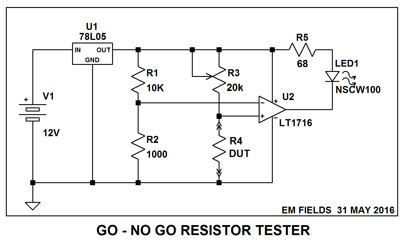
In the circuit shown below, when the DUT's resistance is less than 1000 ohms, LED1 will shine with constant brightness but when the DUT's resistance is greater than 1000 ohms the LED will go out completely.

When the DUT is equal to zero ohms there'll be 500 microamperes through it, and at 1000 ohms the current will fall to 450 microamperes.

U1 is a voltage regulator, and will drop the battery voltage down to a steady 5 volts for the comparator (U1) and is used - along with R1 and R2 - to generate the comparator's reference voltage.

I've shown an LT1716 for the comparator, but any comparator capable of sinking the LED current (about 10mA for the LED shown) will work.

To set up/calibrate the tester you'd use a 1000 ohm known good resistor for R4 and adjust R3 (a 10 turn trimpot would be nice) until the LED just went ON or OFF. Thereafter, any resistor with a resistance greater than your reference resistor would cause the LED to go OFF and with a resistance less than your reference would cause the LED to go ON.

enter image description here

\$\endgroup\$
2
  • \$\begingroup\$ What's the reason for having U1? The LT1716 data sheet says it's good for up tro 44V. \$\endgroup\$
    – Simon B
    Commented May 31, 2016 at 16:38
  • 1
    \$\begingroup\$ @SimonB I think U1 is to give a fixed voltage (acting also as a reference), since OP says the supply voltage would vary. \$\endgroup\$ Commented May 31, 2016 at 16:47

Your Answer

By clicking “Post Your Answer”, you agree to our terms of service and acknowledge you have read our privacy policy.

Not the answer you're looking for? Browse other questions tagged or ask your own question.