How to control the amount of current I drain from a lipo? U=I*R and I know R but how do I control the values of U and I? If the battery has 1000mAh, 10C and 10 V (I made this up), does the battery constantly drain 10 A at 10 V and I have to increase the resistance to lower the current?
-
1\$\begingroup\$ The load will draw whatever current it needs. What are you trying to do? \$\endgroup\$– Matt YoungCommented Jun 12, 2016 at 18:35
-
\$\begingroup\$ Power a motor with a circuit I am making myself, so I am thinking that if I want to control the speed I need to control the current, or do I need just to control the voltage on the wire and the current will adjust automatically? \$\endgroup\$– AlexCommented Jun 12, 2016 at 18:45
-
1\$\begingroup\$ @MattYoung - manifestly untrue. Only loads with control mechanisms (active or passive) draw what they "need" when provided with varying voltages. Others draw what they do, which depending on the voltage may be highly inappropriate \$\endgroup\$– Chris StrattonCommented Jun 12, 2016 at 18:53
-
\$\begingroup\$ @Alex - Conceptually speaking motor control (especially for battery powered devices where efficiency is key) is usually done by pulse-width modulation using switching devices that are as ideally as possible only ever fully on or fully off, to minimize power wasted heating the switch. However, the situation you describe is not one where making initial learning experiments would be wise - best to use a few AA cells and a smaller motor to learn about the concepts first. \$\endgroup\$– Chris StrattonCommented Jun 12, 2016 at 18:56
-
\$\begingroup\$ i am going to use PWM with mosfets. But I don't know if changing the voltage in the mosfets is the only thing I need to do. \$\endgroup\$– AlexCommented Jun 12, 2016 at 20:05
1 Answer
The speed of a DC motor is proportional to the voltage applied to it. Current draw is proportional to torque. If you connect the motor directly to the battery then it will try to spin up to whatever voltage the battery puts out, and the only way to control current will be to vary the load (torque).
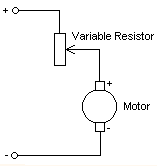
If you could somehow lower the motor's voltage then it would spin slower. Since most loads require less torque at lower rpm, lowering the voltage should also reduce the current. The simplest way to reduce motor voltage is to just put a resistor in series, which drops a voltage proportional to the current flowing through it (Ohm's Law).
So if your motor draws 1A at 10V and you insert a 5Ω resistor in series then the motor will only get 5V, which would slow it down to half speed. If the load requires less torque to spin at this lower speed then current consumption will also drop, causing the voltage and current to reach equilibrium somewhere between 5~10V and below 1A.
However if the load demands more torque then current will increase and the voltage will drop even lower. Changes in loading will cause the motor to speed up and slow down dramatically. If too much load is applied the motor may stall and not be able to start up again.
Another problem with using a resistor is that it will waste power and get hot (Power = Voltage x Current, and the resistor converts that power into heat).
The speed variation problem can be solved by using a transistor with a feedback control loop that varies its 'resistance' to keep the motor voltage constant while allowing it to draw the current it needs. However this 'linear voltage regulator' will still waste power and get hot.
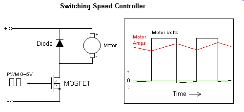
Luckily there is another solution that doesn't waste power - PWM (Pulse Width Modulation). This makes use of the motor's mechanical inertia and inductance to control the speed without having to drop voltage and pass current at the same time.
Switching the motor on and off rapidly causes it to run at a speed proportional to the average voltage, so at 50% PWM it will spin at half speed just like it would with 5V DC. However unlike a resistor or linear regulator, the MOSFET is turned fully on and off so it either drops (almost) no voltage or passes no current, with the result being almost zero power loss.
The diode in this circuit perform two functions. Firstly it prevents the MOSFET from being damaged by the voltage spike (caused by winding inductance) which occurs every time the motor is switched off. Secondly it diverts the spike current back into the motor, improving efficiency and keeping the current going so the motor runs smoother and responds better to PWM control.
-
\$\begingroup\$ Nice answer! One more question: if my mosfet is 30 Amps and 50 V, and the battery has 10 Volts it means that when fully load the circuit will get 10 Volts or ) volts and I just increase or decrease the frequency to change the voltage, right? But if the current trough the mosfet is higher than 30 Amps the mosfet will be fried, right? \$\endgroup\$– AlexCommented Jun 13, 2016 at 12:31
-
\$\begingroup\$ To vary the voltage you change the PWM ratio. 0% PWM (always off) = 0V and 100% PWM (always on) is full battery voltage. To reduce current ripple the PWM frequency should be 3KHz or higher. Your MOSFET will fry if it overheats. Depending on Rdson and heatsinking, this may occur at much less than 30A. Also the motor could draw 3~5 times its rated current at stall, so a '30A' FET may only be safe for a motor rated at 6~10A. Note that to get lowest Rdson the PWM voltage must be high enough to fully turn the FET on. A high voltage FET may need 10V Gate drive. \$\endgroup\$ Commented Jun 13, 2016 at 21:20


