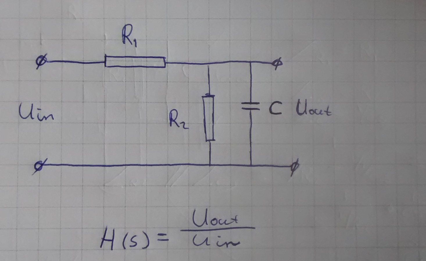
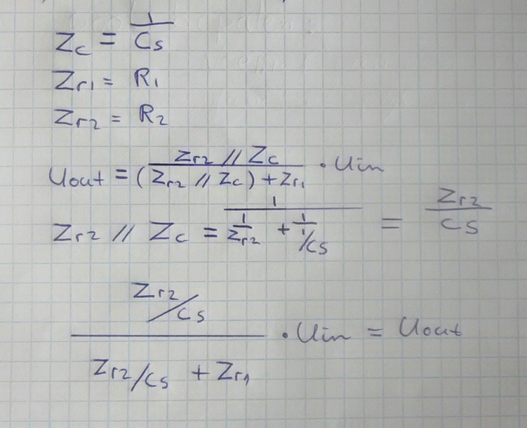
A slightly different approach here and there is nothing I can see wrong with the other answer is to first find the impedance of \$ C \$ in parallel with \$ R_2 \$ from "product over sum" formula for two impedances in parallel.
$$Z_{bot} =\dfrac{R_2 \cdot \dfrac{1}{s \cdot C}}{R_2 + \dfrac{1}{s \cdot C}} = \dfrac{R_2}{1+ s \cdot C \cdot R_2}$$
Now we note that the circuit is a potential divider so
$$H(s) = \dfrac{U_{out}}{U_{in}} = \dfrac{Z{bot}}{Z{top} + Z{bot}}$$
Where \$ Z_{top} \$ is just \$ R_1 \$ and \$ Z_{bot} \$ is the parallel impedance we just calculated.
$$H(s) = \dfrac{\dfrac{R_2}{1+ s \cdot C \cdot R_2}}{R_1 + \dfrac{R_2}{1+ s \cdot C \cdot R_2}} = \dfrac{R_2}{R_1 + R_2} \cdot \dfrac{1}{1 + s \cdot C \cdot \dfrac{R_1 \cdot R_2}{R1+R2}}$$
Writing the transfer function is this way we can easily see by inspection that we have a gain at low frequencies of
$$\dfrac{R_2}{R_1 + R_2}$$
and a single pole making this a low pass filter. The pole is located where
$$\left| s \cdot C \cdot \dfrac{R_1 \cdot R_2}{R1+R2} \right| = 1$$


