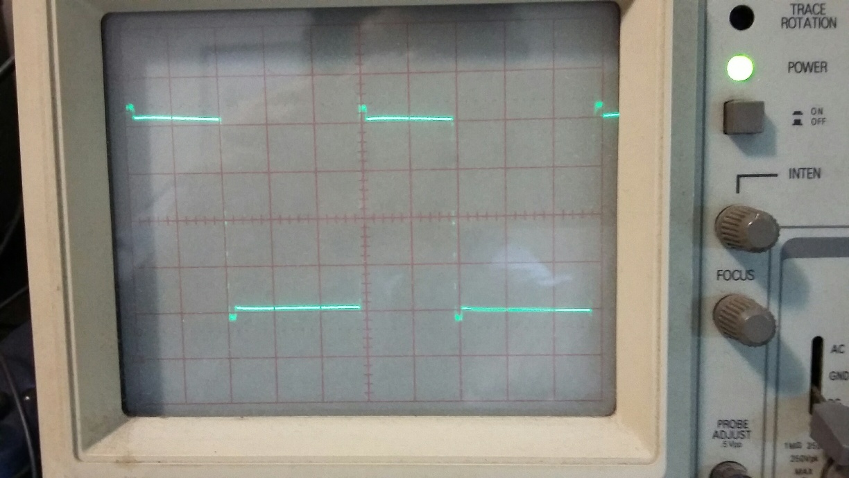
I'm buiding a 60Hz sine wave inverter based on 19Khz PWM generated by a PIC16F883 (lookup table) using a half bridge with 4 x IRF2807 - switching a pair of low-side/high-side. I'm using my own designed MOSFET driver with discrete transistors. I'm feeding the bridge with 12V and using a 700VA transformer to step up the voltage from 12V to 127VAC.
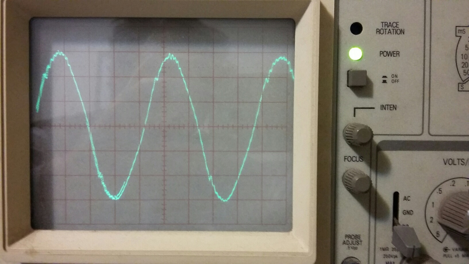
I still have some small wave distortion specially with inductive loads such as a fan motor (in the picture, an example with a 60W/127VAC fan).
Question: Looking at the oscilloscope screen capture, do you guys think I should go further in reducing the deadtime to enhace the wave quality and still be safe to avoid shoot thru current? Or should I keep it and go for the final PCB, since the circuit is still on protoboard, so parasitc inductances may be present. Each vertical division means 10us in the PWM wave. I fixed the duty cyle just to capture the image.
Thank you!


