I am troubleshooting a gas heater and all test results point to the flame sensor but I would like to bench test the flame sensor. Any ideas on how I might set up a test environment with on-hand materials like maybe a burner (camp stove, bunsen) and power source, then stick the flame sensor in the flame and compare the uA current to spec?
-
2\$\begingroup\$ It's cheap so replace it. A measuring setup might cost more. We don't have a crystal ball to know what kind of sensor is it. Usually it is about the LDR CdS, so find appropiate datasheet. \$\endgroup\$– Marko BuršičCommented Jul 1, 2016 at 17:43
-
\$\begingroup\$ I know you're new to this site but don't you think that a photo would be required at the very minimum so that we know what type it is? \$\endgroup\$– TransistorCommented Jul 1, 2016 at 17:44
-
\$\begingroup\$ upperplumbers.co.uk/plumbing/… \$\endgroup\$– JIm DeardenCommented Jul 1, 2016 at 17:44
-
\$\begingroup\$ Cheap is relative. It is certainly cheaper than the Control Board ($500) or the Blower & Motor ($450) at $28. But I already bought the replacement and it exhibits the same symptoms as the original (0.1 - 0.3 uA) when specs say it should be throwing 6.0 uA or thereabouts. I'll add a picture soon. \$\endgroup\$– WDVinAZCommented Jul 1, 2016 at 21:28
3 Answers
The 'sensor' itself is just a wire. If it is positioned correctly in the flame, connected properly and not shorted to ground it will work, period. The circuitry should (with very, very high reliability) cause a shutdown if the sensor is open or shorted.
Testing the circuitry is much more involved, particularly if you need to verify the fail-safe and redundancy characteristics that are required for safety. If it is faulty it should be replaced in accordance with the manufacturer's recommendations and local codes .
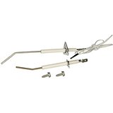
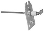
For those unfamiliar with the 'flame rectification' method of flame detection, the 'sensor' looks like this:
The 'flame rod' is a metal wire that extends into the flame The mounting bracket has a ceramic insulator and the flame rod has a spade connector for a wire running back to the electronics. Such an electrode extending into an open flame has diode-like characteristics. The asymmetric conduction (between the rod and the burner, which is grounded) is used to distinguish between shorted, open and resistive conduction (as might be caused by faults or condensation or contamination).
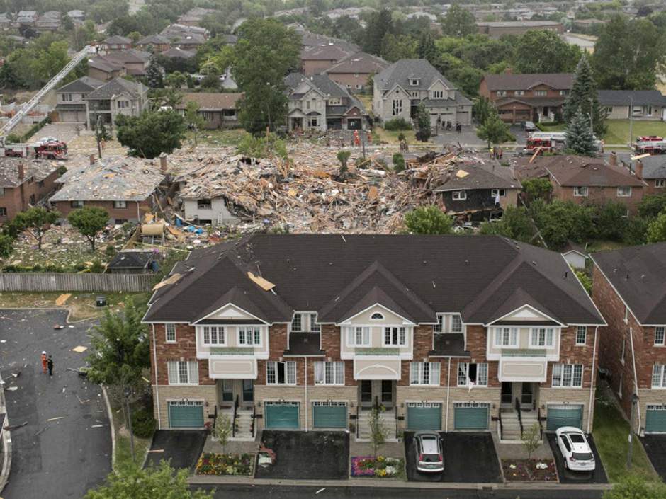
It is extremely important in gas combustion systems to avoid a false positive flame detection output, since that would allow the gas valve to remain open in the absence of a flame. The gas would then continue to flow, mixing with air, until it finds a spark or flame to ignite it, and 'kaboom', as happened recently here (Photo from the National Post):
-
1\$\begingroup\$ depends on the type of sensor, some are based on ionization of the air due to thermal radiation, and some measure the IR radiation. \$\endgroup\$– MaMbaCommented Jul 1, 2016 at 18:01
-
\$\begingroup\$ @MaMba The title specifically says "flame rectification". Many industrial types are solar-blind UV-sensing. \$\endgroup\$ Commented Jul 1, 2016 at 18:03
-
\$\begingroup\$ I certainly don't want to do that to my neighborhood. All I want to do is prove the sensor is good or bad outside of the heater. I'm hoping someone can suggest a simple test setup since none of the safety requirements of actual operation will be needed. \$\endgroup\$– WDVinAZCommented Jul 2, 2016 at 3:20
-
\$\begingroup\$ Nice answer. "The asymmetric conduction (between the rod and the burner, which is grounded) is used ...". Can you explain this bit? What causes the asymmetry and how is it used? \$\endgroup\$ Commented Jul 7, 2016 at 17:02
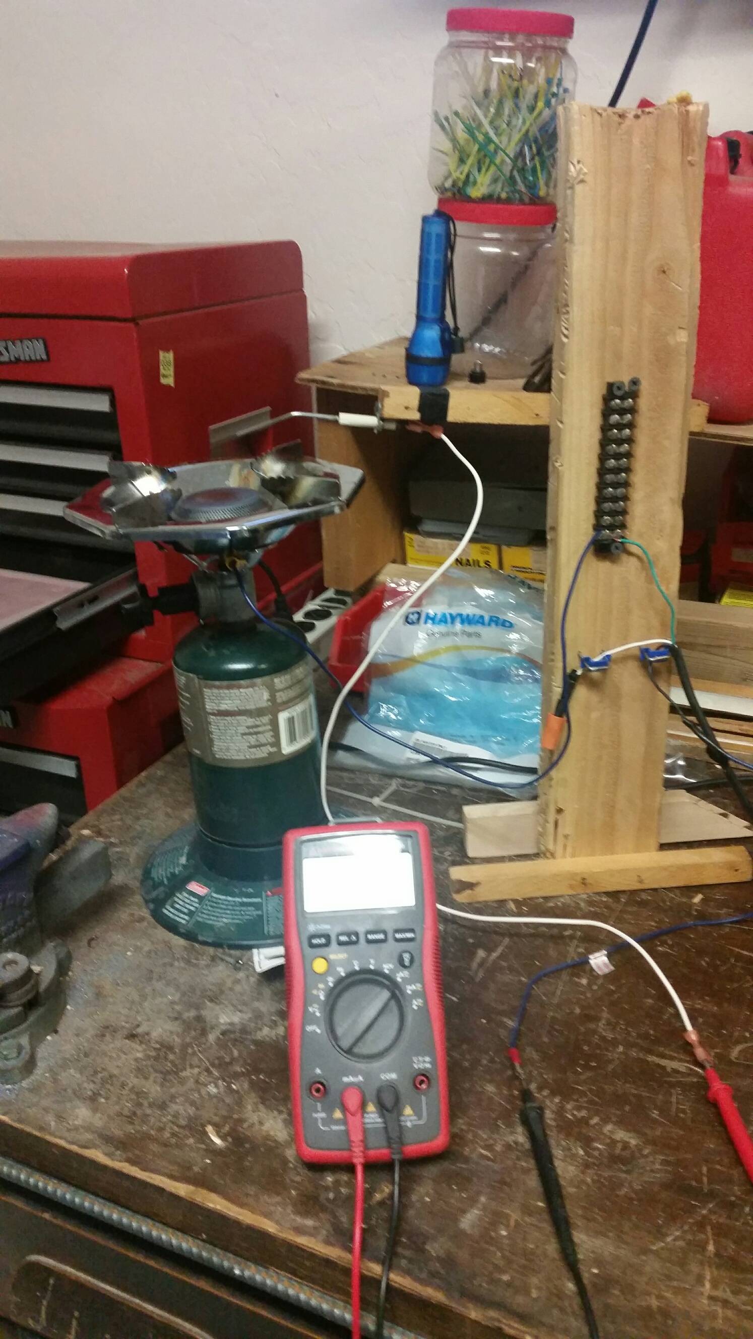
I have set up a bench test that was able to measure uA. Materials: Household 120V, Coleman Camping burner, Flame Sensor. Picture attached. I have since contacted Hayward support and support rep stated that they have no spec on uA, the only criteria for checking the FS is continuity.
-
\$\begingroup\$ I moved the bench test to the heater and hooked it up to the Flame Sensor circuit. I was able to introduce a 6.4 uA current into the circuit. I observe the same error code so I am confident that the Flame Sensor circuit is not the problem unless it is with the control board. \$\endgroup\$– WDVinAZCommented Jul 25, 2016 at 3:09
A bunsen burner provides a similar flame as compared to the pilot flame. That's what I'd use.
The two common failures of the actual flame rod is contamination of the rod surface or contamination of the insulator surface.
The flame rod surface is easily cleaned with a scouring pad.
-
\$\begingroup\$ Before I bought a replacement I checked continuity on the original flame sensor from rod to conductor contact. There was none so I cleaned with steel wool. Still none. So I rubbed with emory cloth until continuity was restored. FS still only conducted at 0.1 - 0.3 uA. There is 79.9 VAC at FS connector on control board to burner base. The replacement FS has continuity but conducts only same limited uA. I'm thinking there is some other underlying problem but I would like to see either FS work to spec before investigating deeper (like adjusting gas pressure in light of pic by Spehro above! \$\endgroup\$– WDVinAZCommented Jul 2, 2016 at 15:05


