0
\$\begingroup\$

I'm trying to understand the concept of drawing current.

I read in a site(method 10) that Arduino (ATmega328P) can be damaged if i set ten I/O pins to be high and draw 20mA from each one at the same time.

Currently i have made a circuit that uses three L293D (page 5 at the datasheet for the electrical characteristics) to drive three stepper motors and it works fine.

To drive the L293D i use (3x4) twelve pins and in this configuration these are not high at the same time but when stopped (the motors) all the twelve I/O pins are set to low. (these pins control the logic of the L293D, i use a separate power supply for the motors)

Now i read the L293D datasheet and it has the following ratings

I-IH High-level input current 0.2 μA
I-IL  Low-level input current 0.2 μA
                                                           TYP   MAX
I-CC1 Logic supply current -> All outputs at high level   13mA   22mA
                              All outputs at low          35mA   60mA
                              All outputs high impedance   8mA   24mA

Can someone explain me a bit these ratings. Do i overload the pins by drawing 35mA when all outputs are low and if i do so why there is no damage?

What is "all outputs high impedance"?

Now i don't really care about this specific personal project, but the general logic about current ratings.

\$\endgroup\$
3
  • \$\begingroup\$ Please add links to any devices referenced in your question. By "10" pins I presume you mean I/O (input/output) pins? \$\endgroup\$
    – Transistor
    Commented Jul 5, 2016 at 18:31
  • \$\begingroup\$ You've referenced a "L293d" but haven't provided a link to the datasheet. If the link is there more of us will click it than would go searching for it and you will improve your chances of getting a good answer. Say what page the extract is on too. i.e., Make it easy for those who are helping you for free. \$\endgroup\$
    – Transistor
    Commented Jul 5, 2016 at 18:35
  • \$\begingroup\$ You are right, electrical engineering stack exchange is a great site, i think the best out there. Thanks for all the help \$\endgroup\$
    – John Am
    Commented Jul 5, 2016 at 18:50

2 Answers 2

3
\$\begingroup\$
  • The input currents tell you what the chip will require from the device that's driving it. i.e., your micro-controller.
  • The logic supply current is what is required to run the logic in the chip. The datasheet shows some of the internal transistors, etc.
  • The high impedance refers to the ability to disable the outputs: neither the pull-up transistor is on nor the pull-down transistor so the output effectively isn't connected to anything and appears as a high impedance or high resistance - effectively an open-circuit.

enter image description here

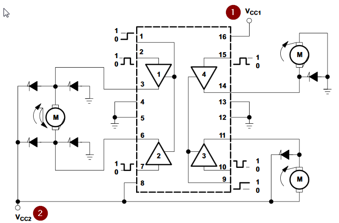
Figure 1. Logic supply (1) and motor supply (2).

The datasheet says:

A VCC1 terminal, separate from VCC2, is provided for the logic inputs to minimize device power dissipation.

As is good practice on many motor systems a separate supply is used for the logic and motors. The 35 mA refers to Vcc1. You can pull up to 1 A continuously on Vcc2, if I read the datasheet correctly.

\$\endgroup\$
2
  • \$\begingroup\$ Thanks. So the "logic supply current" is what the whole L293D draw from the Arduino power supply (5V) and it says the typical rate is 35mA? \$\endgroup\$
    – John Am
    Commented Jul 5, 2016 at 19:03
  • \$\begingroup\$ Yes, if your Arduino voltage regulator has 35 mA to spare then you can power this driver chip from it through Vcc1. You could power your motors from an unregulated supply - maybe the one that's feeding the Arduino. The motors won't care if the voltage varies a couple of volts so they don't need a regulated supply. \$\endgroup\$
    – Transistor
    Commented Jul 5, 2016 at 20:27
1
\$\begingroup\$

Per the spec sheet the L293D draws a maximum of 100uA per pin, so that is the only load your Arduino will see per pin. You will not even draw 1mA per pin. An option is to add a 10K resistor from each control pin to ground so during startup the motors are kept in an OFF state until your program is running and takes control of those 10 pins.

"all outputs high impedance'

This means that the pins are floating and do not source or sink any current, as if they did not exist.

\$\endgroup\$
5
  • \$\begingroup\$ So the "High-level input current" and the "Low-level input current" max rating is the one i should read (100μΑ and -100μΑ maximum)? \$\endgroup\$
    – John Am
    Commented Jul 5, 2016 at 18:54
  • \$\begingroup\$ @JohnAm. Yes, in terms of the loading the Arduino sees. The input pins for the L293D draw almost no current, so that is why I suggested the 10K pull-down resistors to act as a minimum load and keep the IC and motors OFF (high-impedance) until your software can control the I/O pins during boot-up. \$\endgroup\$
    – user105652
    Commented Jul 5, 2016 at 18:58
  • \$\begingroup\$ Thanks for the info. I'll have to study what happens in power on of the whole circuit. Now i start the Arduino and after i upload the program i connect the power supply to the motors. \$\endgroup\$
    – John Am
    Commented Jul 5, 2016 at 19:05
  • \$\begingroup\$ @JohnAm. The L293D motor driver is designed to handle the motor currents as specified, so the Arduino does not see the load the motors present to the L293D IC. The IC is both a buffer and driver, with outputs that can be shut off. (high-impedance) \$\endgroup\$
    – user105652
    Commented Jul 5, 2016 at 19:11
  • \$\begingroup\$ Thanks you very much. I will select the other answer as the right one because it is more detailed but thanks for your time, both answers are addressing my question correctly. \$\endgroup\$
    – John Am
    Commented Jul 5, 2016 at 19:13

Your Answer

By clicking “Post Your Answer”, you agree to our terms of service and acknowledge you have read our privacy policy.

Not the answer you're looking for? Browse other questions tagged or ask your own question.