I'm designing a musical instrument in which two oscillators (one based on a Quad NAND gate, the other on a 555) are controlled by a signal from a condenser microphone. At the moment the mic is being phantom powered via my computer audio interface, then coming from an output of the interface and entering the circuit at line level.
I now need to add a 48v phantom power circuit so that the mic can be powered directly from the instrument. I've purchased a 12v-48v DC-DC converter (this one) which seems to work fine. My question is about how to incorporate this without damaging the subsequent circuitry.
This is essentially my proposed circuit. Phantom power works by putting both signal pins of the XLR at 48v with respect to ground; the mic signal is amplified by a LM386N-4 power amp and this signal controls the oscillators via an LED-LDR arrangement. I haven't included the rest of the circuit, since I'm mainly worried about whether the phantom power will damage the LM386N-4. (I'm also not too bothered about audio fidelity, as the mic signal is only used to control the oscillators, and won't be directly audible - it just needs to be high enough going into the rest of the circuit):
What I'm particularly worried about is blowing up the LM386N, perhaps by it internally referencing either of its inputs to ground (and hence seeing 48v across some of its internal structure). Will this circuit work, in the sense that it will amplify the mic signal without damaging anything?
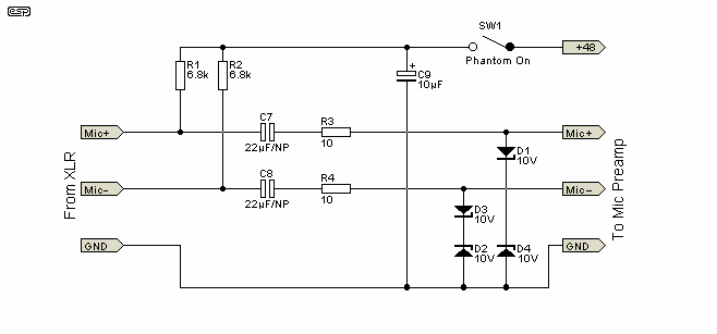
Incidentally, the phantom power circuit proposed here suggests putting a pair of zener diodes between each signal line and ground, as shown below - would using these in my proposed circuit prevent damage to the LM386N-4, or any subsequent circuitry?


