1
\$\begingroup\$

Just today I was suddenly curious to know how a closed circuit works. I have learned some basics so far. I understand how it is supposed to work and mostly why. But some things elude me, and my searches to understand the behavior of current always leads back to the conventional vs electron flow debates.

Would appreciate help in wrapping my head around some concepts. I likely won't pursue anything further, I really just want to understand how the current moves.
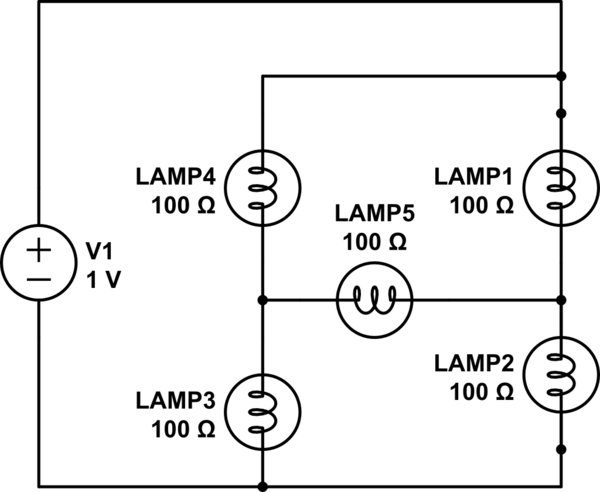
schematic

simulate this circuit – Schematic created using CircuitLab

I have no idea if this circuit actually works, but ignoring the units and sticking to the layout it's the best way I can ask by example. So I guess using conventional flow, if the current reaches that first fork, what happens?

Does the current travel to both LAMP1 and LAMP4 regardless of resistance? Does the amperage of the current now split in half or does it remain equal or proportional based on resistance for both paths?

Assuming the current did travel to LAMP4, would it from there still try and travel to LAMP5 or would it only continue to LAMP3 because the negative end of the battery is not in that direction?

And what about LAMP5 anyway.. would it be receiving current from both sides?

Would the current amperage leaving LAMP3 possibly be different than that leaving LAMP2? If so, what happens when they meet where the wires intersect?

Would really appreciate the insight.

\$\endgroup\$
3
  • 1
    \$\begingroup\$ May I recommend that you shorten your question to remove the capacitor. Then you circuit is easier to explain. Ask about capacitors in a separate question is my advice. \$\endgroup\$
    – Andy aka
    Commented Jul 26, 2016 at 11:49
  • \$\begingroup\$ Your lamps are connected in a bridge circuit that is not, generally, solvable by Ohm's Law. With the resistance values chosen, you've hit on a special case where the bridge is balanced, so in this case the current does divide equally at the top junction. Best to start with a simpler series/parallel configuration and, as Andy recommends, omit the capacitor for the time being. \$\endgroup\$
    – Chu
    Commented Jul 26, 2016 at 12:48
  • \$\begingroup\$ Does this help? falstad.com/circuit/… \$\endgroup\$
    – endolith
    Commented Jan 9, 2018 at 21:22

5 Answers 5

0
\$\begingroup\$

I'm not considering the effects of the capacitor because the OP needs to understand basic DC voltage and current relationships first and the capacitor is too complex to cover at this level.

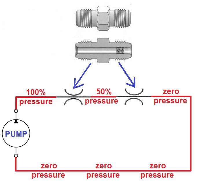
Using the water pressure and flow analogy consider this: -

enter image description here

To the left we have a pump generating pressure and I've called the pressure it generates "100%". I've added two fluid restrictors to form a "circuit". The flow of fluid returns back to the pump and I've named that return node "zero pressure". There may be some pressure in the return path relative to atmospheric pressure but that is of no importance, after all we don't care what voltage the moon is when we say ground is zero volts.

Important to note - the node between the two restrictors is 50% pressure. Think about this because it is important.

Also think about the flow of fluid.

You could simply equate the flow to \$\dfrac{pressure}{resistance}\$

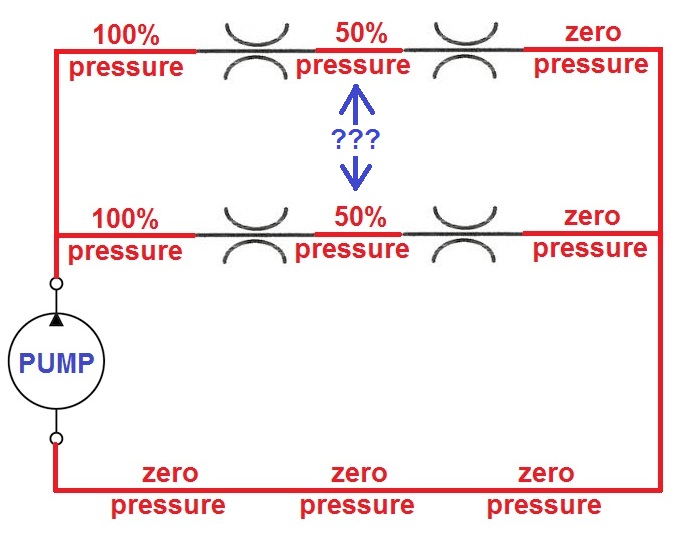
Now imagine I doubled up on the restrictors and made this circuit: -

enter image description here

Note the blue double arrow and question marks - ask your self what flow would exist between those two points if a hose were connected.

\$\endgroup\$
3
  • \$\begingroup\$ It looks to me that if those were connected they would both be giving a pressure of 50% through it. But if they are competing, equal forces.. then its 0? Water would fill that hose.. but an electrical current would not?? \$\endgroup\$
    – Chibi
    Commented Jul 26, 2016 at 20:04
  • \$\begingroup\$ @chibi correct, there would be no current flow or fluid flow. \$\endgroup\$
    – Andy aka
    Commented Jul 26, 2016 at 20:30
  • \$\begingroup\$ @chibi By the way, when using the water analogy for circuits, you should think of all pipes as already full of water. \$\endgroup\$
    – Justin
    Commented Jul 26, 2016 at 20:47
1
\$\begingroup\$

See other questions on the basics e.g. Is voltage the speed of electrons?

For understanding current, it's much easier to forget the electrons and stick with the conventional model. The other important thing to understand about current is that it's not exactly like water - it doesn't set off into the circuit and then "decide" where to go. Current is more like a bicycle chain: there has to be a complete loop for it to move.

So how does it know whether there's a complete loop or not? This is where the voltage is important. Voltage represents a level of energy in the electric field between two points. The field inside a conductor "wants" to flatten out so the level is the same everywhere. So if you attach a conductor to a battery terminal at one end, the other end will acquire the same potential.

What happens when two fields of different potential meet? That is when a current starts to flow, as the fields attempt to equalise potential. You get an electrical wave propagating out from where the switch closed to make the circuit complete.

The waves travel at a high fraction of the speed of light. This isn't relevant to little circuits with batteries and lightbulbs, but it is very relevant when you're trying to use switching to send digital information.

(This discussion does not account for superconductors or semiconductors. It doesn't address the capacitor either, but what a capacitor does is store energy through changes in electrical field strength. It does not store current; it can be said to store voltage, but the energy associated with that voltage is what's important.)

\$\endgroup\$
0
\$\begingroup\$

Let's have a look, first we ignore the capacitor for your current question.

The resistors (lamps) all have the same value. We assume that we have ideal, or at least identical wires (let's just say the wires have 0 ohm). The current splits exactly 50/50 because we have the same resistance in every path. Because we have the same resitance everywhere, we have the same potential on every lamp (except lamp5).

Now to lamp5. In theory there is no current running in this path. That's because we have the same potential on the left and right node and when there is no difference in the potential there is no voltage drop (Just imagine two forces with the same power pressing against each other - no one moves). When there is no voltage drop there is no current (U = R*I, U = 0 so I is 0 too).

\$\endgroup\$
2
  • \$\begingroup\$ So if I understand, ignoring the capacitor, if the current was 100 it would split at the fork and 50 would go to LAMP4 + LAMP3 and 50 to LAMP1 + LAMP2. LAMP5 is cancelled out. Will the current become 100 again when the two 50's meet up again? (pretending that the lamps didn't decrease anything.. if they even would) \$\endgroup\$
    – Chibi
    Commented Jul 26, 2016 at 20:15
  • \$\begingroup\$ Current doesn't 'decrease' as it flows around a circuit. Whatever flows in to a component, flows out at the other end. Also, the sum of the currents towards any junction is equal to the sum of the currents away from that junction. \$\endgroup\$
    – Chu
    Commented Jul 26, 2016 at 20:59
0
\$\begingroup\$

In an ideal circuit, LAMP5 will see zero voltage (and, consequently, zero current) forever. Note that real-life parts are not ideal. Moreover, most light sources either have their resistance dependent on their internal temperature (hence, power) or defy the Ohm’s law outright. For incandescent lamps, for example, the resistance/temperature dependence results in a strong positive feedback in serial circuits. Gas discharge lamps are even worse due to their unpredictability. Conclusion: in the real life one can’t be sure that LAMP5 will always be dark.

\$\endgroup\$
-1
\$\begingroup\$

Quick check:

Someone with experience may look at this circuit and assume the power is off at first. (Otherwise the answer is simple, all lamps are off.) Then when the power is applied current will flow through all the bulbs except 5. This is because you place 5 at a balancing point of sorts. In order for current to flow through a load the voltage has to be different at each end. But your design is symmetrical so there is not a voltage difference. Going on, as time passes the capacitor will charge up and the current will stop. All the lights will go out.

Longer way:

You can either anylize this circuit using the Thevenin equivalent or the Norton equivalent. One's just saying the cup is half empty and the other half full. Same thing. Now, the tricky bit is that you have included a capacitor. So (big jump) you need to use differential equations! This MIT (capacitor / resistor) work shop should actually address most if not all your questions you have asked above.

A word about capacitors:

Let us consider an ideal capacitor. Such a device is made of 2 sheets of metal separated by a thin insulator. If you "push" electrons into one metal sheet (charge it negative) you influence the other metal sheet to push electrons out (charge it positive). It is very easy to charge on an empty capacitor. So the capacitor looks like a short. As time passes, the capacitor gets saturated (gets full). Now it is practically impossible to add more charge. The capacitor now looks like an open. If you remove this ideal capacitor it would retain this charge. You could use it later as a power source if you like. However, in the real world, we can only approach what an ideal capacitor is. So, eventually, the charge will leak away.

\$\endgroup\$
3
  • \$\begingroup\$ A capacitor is not an active component. \$\endgroup\$
    – Curd
    Commented Jul 26, 2016 at 12:13
  • \$\begingroup\$ Phasor analysis can only be used for analyzing the steady state with sinusoidal sources. Neither are we looking at the steady state (we are looking at the transient behaviour) of the circuit nor are there any sinusoidal sources. (If you want PA could be applied if the switching on is treated as superposition of (infinitely) many sinusoidal sources but I doubt if that makes it more simple) \$\endgroup\$
    – Curd
    Commented Jul 26, 2016 at 12:18
  • \$\begingroup\$ Good points, I'll correct the answer. \$\endgroup\$
    – st2000
    Commented Jul 26, 2016 at 12:26

Your Answer

By clicking “Post Your Answer”, you agree to our terms of service and acknowledge you have read our privacy policy.

Not the answer you're looking for? Browse other questions tagged or ask your own question.