0
\$\begingroup\$

I'm working on PCB design that will typically be battery powered. However, the device needs to be programmed and thus will be plugged into a computer occasionally.

I'm running into the problem of switching between a battery supply and a PC power supply, and specifically making sure I won't be applying power from both sources at the same time.

Is the general method to use relay logic to switch between power supplies? I assume I could design something that disconnects the battery supply when the device is connected to the PC. However, I assume this is a common problem and am curious if there are other methods for addressing this.

\$\endgroup\$
4
  • \$\begingroup\$ Can you avoid supplying power from PC? Don't apply power from the PC if you can avoid it. \$\endgroup\$ Commented Aug 17, 2016 at 20:09
  • \$\begingroup\$ @NickAlexeev That was something else that I was thinking. It would be the easiest solution. It's just a matter of wasting batteries during the programming stage. This minor inconvenience may be less than the inconvenience of adding additional components though. \$\endgroup\$
    – Izzo
    Commented Aug 17, 2016 at 20:11
  • \$\begingroup\$ If you want to avoid voltage dips and spikes I would suggest conencting both sources to the device through suitable low drop out voltage regulators with the same voltage output of have the mains powered regulator supply 0.1V more so it will carry the load unless it fails. Check that the LDOs will ignore reverse drive and such. You can then use a shut-down pin (sometimes available) as a power switch. \$\endgroup\$
    – KalleMP
    Commented Aug 17, 2016 at 22:15
  • \$\begingroup\$ Devices such as the following are an option. - linear.com/product/LT1579 \$\endgroup\$
    – KalleMP
    Commented Aug 17, 2016 at 22:17

1 Answer 1

1
\$\begingroup\$

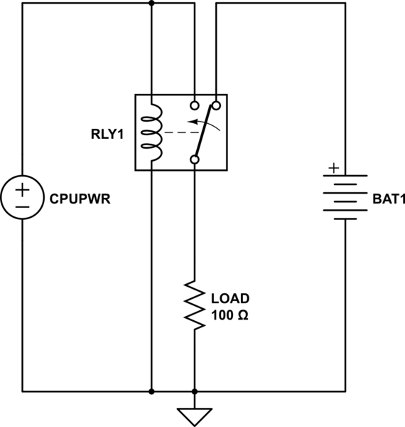
A relay would be a nice easy solution. The circuit below would power the load from the battery until you applied CPU power. Keep in mind there will be a brief changeover period where no power is applied; as long as this is ok this is an easy way.

schematic

simulate this circuit – Schematic created using CircuitLab

\$\endgroup\$
5
  • \$\begingroup\$ That would be perfect for my application. That would be considered a single pole dual throw relay correct? \$\endgroup\$
    – Izzo
    Commented Aug 17, 2016 at 19:51
  • \$\begingroup\$ Yep, and you may also see them listed as "Form C" \$\endgroup\$
    – Jim
    Commented Aug 17, 2016 at 19:53
  • \$\begingroup\$ Another question: In the case I decided to implement a solid state relay (photo relay), would I need to be concerned about the instantaneous switching point? Due to the fact that I would no longer be relying on a mechanical switch, but simply an internal LED? \$\endgroup\$
    – Izzo
    Commented Aug 17, 2016 at 19:59
  • \$\begingroup\$ Tough to say without a schematic + part number. I doubt its truly an "instantaneous" switch and more likely there's a very small break-before-make period. Obviously solid state switching is much faster than mechanical. Could you link to the photo relay you're thinking of? \$\endgroup\$
    – Jim
    Commented Aug 17, 2016 at 20:31
  • \$\begingroup\$ Hi Jim, thanks for looking at this. I was looking primarily at this one right here: ixysic.com/home/PDFs.nsf/www/Lcc110.pdf/$File/Lcc110.pdf \$\endgroup\$
    – Izzo
    Commented Aug 17, 2016 at 22:04

Your Answer

By clicking “Post Your Answer”, you agree to our terms of service and acknowledge you have read our privacy policy.

Not the answer you're looking for? Browse other questions tagged or ask your own question.