1
\$\begingroup\$

Due to the unavailability of EEVBlog's uCurrent (A tool designed to assist with measuring low standby currents) I would like to build my own similar tool, in particular I would like to achieve a higher bandwidth to allow better operation when used with an oscilloscope for analyzing micro-controller sleep current.

While planning my design I came across the Analog Devices AD8421 at the $15 mark it is a reasonably pricey op-amp but thought it would make a good selection for a task like this for the following reasons.

  • High Input Impedance (30Gohms)
  • High gain range (1-10000)
  • Good bandwidth at high gains
  • Low input noise
  • Large supply voltage range

I am not used to designing gear with such high-speed amplifiers, is there any gotchas to be aware of. Could it really be as simple as the below circuit. The idea being to break into the current path somewhere (at a voltage within 9V of earth) and connect through J1, and then to hook an oscilloscope to J2.

I am more interested in getting an accurate waveform shape with low noise than an accurate magnitude.

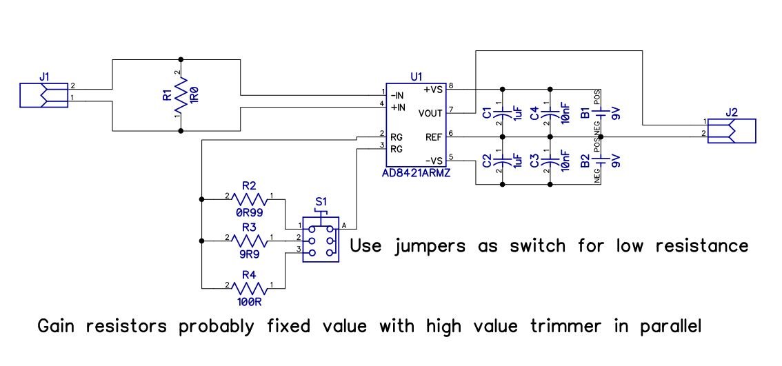
enter image description here

\$\endgroup\$
5
  • 1
    \$\begingroup\$ One gotch I can see. You need to tye at least one of the input pins (IN+ or IN-) to your (virtual) ground, that is pin 2 of J2. Ref page 22 of the datasheet. Your case is like the transformer or the thermocouple example. \$\endgroup\$
    – Bernie Nor
    Commented Aug 31, 2016 at 7:21
  • \$\begingroup\$ Why is that, from what I read as long as my shunt is within approx 2v of the rails it should work correctly. \$\endgroup\$
    – Hugoagogo
    Commented Aug 31, 2016 at 7:25
  • \$\begingroup\$ As long as that is true, you should be ok. I would put a resistor there in any case. Like a 100 k or so. Input pins without any ground reference is not good thing in my book. \$\endgroup\$
    – Bernie Nor
    Commented Aug 31, 2016 at 7:26
  • \$\begingroup\$ 100k would introduce a significant offset if the shunt is inserted on the high side of a device, assuming even a 3.3V circuit, that is 33uA which is pretty significant in terms of sleep currents. I would probably connect 0V on the circuit under test to J2- \$\endgroup\$
    – Hugoagogo
    Commented Aug 31, 2016 at 7:37
  • \$\begingroup\$ If the priority is on the waveform shape the AR version of the AD8421 should be enough. That version only costs <6€ here (Mouser). So you probably saw and cited the pricing of the BR version. \$\endgroup\$
    – Grebu
    Commented Aug 31, 2016 at 9:02

1 Answer 1

2
\$\begingroup\$

If you are really pushing the bandwidth then the parasitic capacitance of the jumpers and "spare" gain setting resistors will cause a peak in the frequency response at low gains that may not be acceptable. See figure 21 in the data sheet for the basic clues at low gain with what would be a simple small resistor across RG terminals. You are significantly extending this with the jumpers and "spare" resistors.

As pointed out in a comment, you need to tie the measurement terminals loosely to ground - see "input bias current return path" on pg 22 of DS. This may cause a common mode noise problem if the resistance for leaking the current is too high and you are at high gain.

Be also aware of the input range especially when the supply voltage is low. You have a negative supply of 9 V and this means the voltage range of the inputs can go as low as -6.7 volts before hitting problems. It's less problematic on positive voltages.

Make sure you use high stability re

\$\endgroup\$
3
  • \$\begingroup\$ Is there any way to estimate the effect of the capacitance of the jumpers, I presume having a jumper at each end of the resistors would probably help slightly. \$\endgroup\$
    – Hugoagogo
    Commented Aug 31, 2016 at 7:51
  • \$\begingroup\$ In addition they mention the device can operate with gains up to 10k but all the graphs only show 1k, can I more or less draw a Line through the knees of the graphs to extrapolate. \$\endgroup\$
    – Hugoagogo
    Commented Aug 31, 2016 at 7:52
  • \$\begingroup\$ Balancing will help for sure but if the leakage capacitance across the "resistor" is increased so will the gain at higher frequencies. Regards operating at 10k gain I have to suggest you speak with ADI - they do have a forum where you can ask questions. \$\endgroup\$
    – Andy aka
    Commented Aug 31, 2016 at 7:56

Your Answer

By clicking “Post Your Answer”, you agree to our terms of service and acknowledge you have read our privacy policy.

Not the answer you're looking for? Browse other questions tagged or ask your own question.