1
\$\begingroup\$

schematic

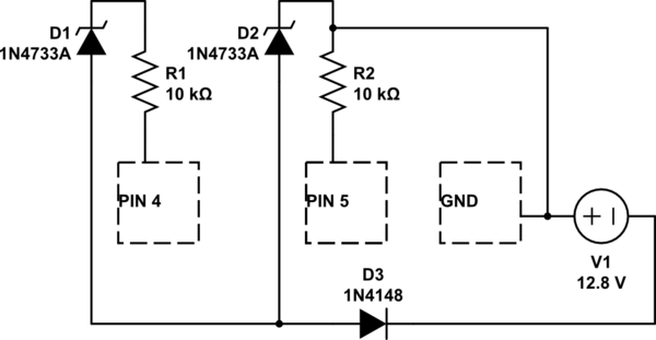
simulate this circuit – Schematic created using CircuitLab

Due to some bad late-night wiring, I ended up with the above circuit. Pins 4 and 5 are digital pins configured as inputs. I can confirm that zener d2 is blown.

The arduino seems to be working relatively fine, accepting new sketches, blinking the internal LED according to the programming logic etc. One exception is that external signals as low as 1.8V are consistently being registered as HIGH by the arduino. I tested this on digital pins 7 and 8 as well.

I would like to ask what the probable damage is, and if replacing the atmega chip would be advised?

EDIT: One thing I forgot to mention is that the arduino was being powered by a seperate 7.2V source through the power jack.

\$\endgroup\$
10
  • \$\begingroup\$ What's the normal threshold for registering a HIGH? Was the - of the 12V connected to anything other than Arduino ground? I think you may have just blown up the Zener. \$\endgroup\$
    – pjc50
    Commented Sep 13, 2016 at 10:05
  • \$\begingroup\$ Normal threshold is 3V. \$\endgroup\$
    – Lkz
    Commented Sep 13, 2016 at 10:07
  • \$\begingroup\$ I hope you are right. No that was pretty much the circuit \$\endgroup\$
    – Lkz
    Commented Sep 13, 2016 at 10:09
  • \$\begingroup\$ Are you sure about that 3V? 1.8 sounds like the inputs are configuerd for TTL levels. \$\endgroup\$ Commented Sep 13, 2016 at 10:09
  • \$\begingroup\$ From the ardunio website: "When a pin is configured as an INPUT with pinMode(), and read with digitalRead(), the Arduino (Atmega) will report HIGH if: a voltage greater than 3 volts is present at the pin (5V boards)" arduino.cc/en/Tutorial/DigitalPins \$\endgroup\$
    – Lkz
    Commented Sep 13, 2016 at 10:14

2 Answers 2

0
\$\begingroup\$

Because the +V was connected to GND, Pin5 (through R2) and Pin4 (through D1 and R1), the only voltage path I can see is through D2 (reversed) and D3. Since D2 is blown (short, I assume), D3 would have taken a fair hit too - how is it?

And 1.8V can still be High to a 328P. According to the datasheet, VIL (Input Low) is maximum 0.3*VCC (or 1.5V), and VIH (Input High) is minimum 0.6*VCC (or 3.0V). So 1.8V is in-between.

EDIT: Just because the Arduino was being powered by the jack shouldn't have caused any problems because V1- wasn't anywhere near Arduino ground. Yes you had V1+ connected to the Arduino ground, and a totally independent circuit going to V1-, but V1+ wasn't relative to the Arduino at all - or am I wrong?

\$\endgroup\$
6
  • \$\begingroup\$ The zener failed to short. I am measuring continuity in both directions. \$\endgroup\$
    – Lkz
    Commented Sep 13, 2016 at 10:39
  • \$\begingroup\$ @Lkeyte5r OK then. \$\endgroup\$ Commented Sep 13, 2016 at 10:41
  • \$\begingroup\$ I think I will replace D3 for good measure, although it seems to be fine. Regarding the input high/low levels, that seems to contradict the arduino page arduino.cc/en/Reference/Constants: When a pin is configured as an INPUT with pinMode(), and read with digitalRead(), the Arduino (Atmega) will report HIGH if: a voltage greater than 3 volts is present at the pin (5V boards); \$\endgroup\$
    – Lkz
    Commented Sep 13, 2016 at 10:42
  • \$\begingroup\$ I'm reporting directly from the ATMega328P Datasheet: atmel.com/images/… \$\endgroup\$ Commented Sep 13, 2016 at 10:43
  • \$\begingroup\$ I am talking specifically about input HIGH though, which is, as you said, minimum 0.6*Vcc=3V. For example, in testing for a high voltage (TRUE/FALSE) on pin 4, the code would be if(digitalRead(4,HIGH)) or if(!digitalRead(4,HIGH)). I.e. without even considering whether the input is LOW or not. \$\endgroup\$
    – Lkz
    Commented Sep 13, 2016 at 10:55
0
\$\begingroup\$

Your mistake probably only took out the zeners. You don't say what the zener voltage is, but I'm assuming well below 12 V.

The 10 kΩ resistors should have protected the processor pins from physical damage. You don't say what voltage the processor is running at. Even if it was 3.3 V, that leaves 8.6 V across the resistors, which would cause less than a milliamp to flow thru the protection diodes. The chip may not operate correctly, but probably didn't get damaged.

There is one exception to this, which is if the chip was powered up during the time the 12 V was applied. That could cause it to become a big SCR that latches on across the power pins. Depending on how beefy the power supply was, this could damage the chip.

1.8 V being interpreted as a logic high isn't itself a problem without a spec. For example, with 3.3 V power and the high/low guaranteed thresholds being 40% and 60% of the supply, anything above 1.3 V could be interpreted as high. Without proper specs, you can't say there is anything broken here.

Pin voltage specs

You say the "high voltage" spec is 60% of the power voltage, which in this case was 5 V. First, just "high voltage" isn't the name of any pin spec. Actually read the datasheet. You are probably quoting the minimum guaranteed high voltage, but that's not the relevant spec here. That's the voltage above which the chip always promises to report a logic high level.

What you want to know is below what voltage it promises to always report a logic low level. Anything above that level could be interpreted as high, so actually getting a high level doesn't prove anything is wrong. For example, if the maximum guaranteed logic low level is 30% of the power voltage, then you only have a problem if you get a logic high with less than 1.5 V in.
\$\endgroup\$
1
  • \$\begingroup\$ The zeners are 4.7V. The atmega328p used in the arduino uno runs at 5V, and a high voltage is 0.6*VCC (or 3.0V). Yes the chip was on at the time the 12V was applied. I will look into the SCR possibility. \$\endgroup\$
    – Lkz
    Commented Sep 13, 2016 at 11:02

Your Answer

By clicking “Post Your Answer”, you agree to our terms of service and acknowledge you have read our privacy policy.

Not the answer you're looking for? Browse other questions tagged or ask your own question.