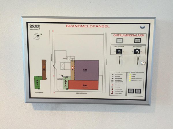
The schematic below is the input circuit of a signalling PCB, which we buy from one of our suppliers of fire detection systems. Said PCB has to be built into a so called geographic evacuation panel which allows firemen to see in which zone of a building a fire has started, and as such is part of a safety system.
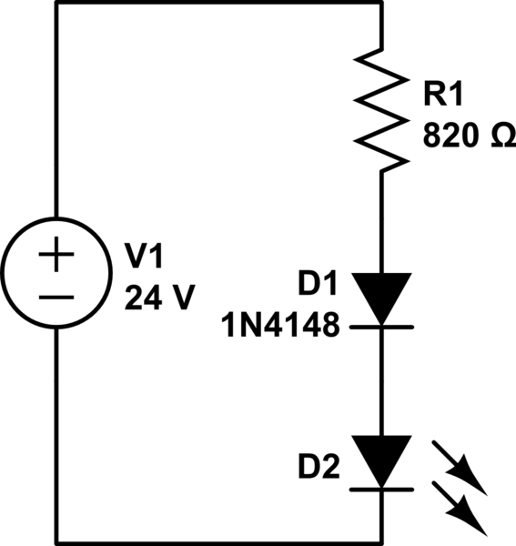
simulate this circuit – Schematic created using CircuitLab
The LED shown is actually the IR LED of an optocoupler (needed for reasons of common mode rejection). Each fire detection zone has such an input. The optocoupler's outputs are fed into an Atmel MCU where they are processed in order to light certain LEDs on a floor plan of the building. In the absence of any input signals, the MCU will reset all LEDs on the panel.
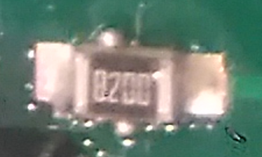
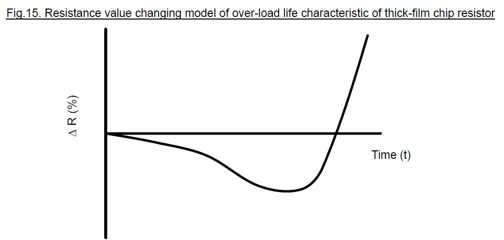
The 820 ohm resistor is an SMD type, and from its dimensions I estimate it to be package 0805 and as such it is rated for 125mW. Documentation from our supplier claims the input voltage range is from 2.2 up to 24V. This is by design, in order to support many brands of fire detection computer. Not all, but a number of systems do actually output 24V. By my own calculations the resistor dissipates about 600mW at 24V input, assuming a total forward voltage of 1.9V for both diode and LED. Actually applying 24V at the input for as short as 5 seconds makes the resistor heat up so much that you can't touch it. At this point the input current is about 26 mA. As I am not very experienced with SMD components, being out of electronics for many years, I need to know if there is any risk that the resistor will burn out, and the panel will not do what is is designed for, potentially resulting in the loss of human life.
The moment the fire service can eyeball the panel is on average first detection + 15 minutes. This means that the resistors in the activated inputs will be subjected to those conditions for at least 15 minutes, in densely populated areas. In rural areas with less firefighting personnel this can be even longer.
Authoritative answers, or links to them, are highly appreciated.
Picture of a geographic panel:
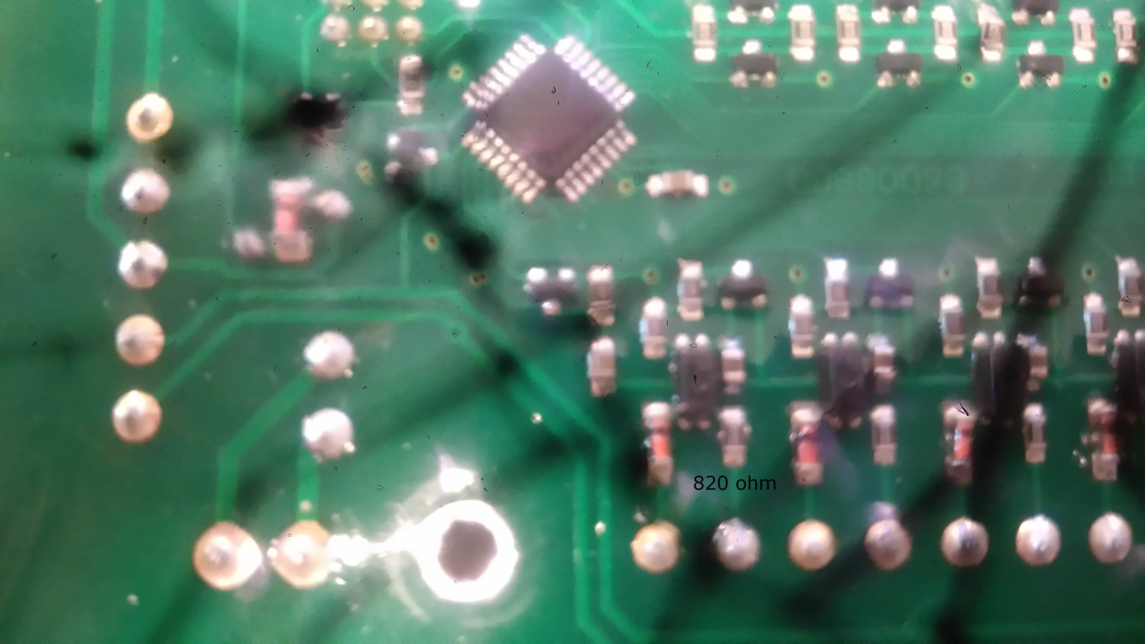
Picture of board with input circuit:
There are eight identical input circuits. I added the text "820 ohm" below one of the resistors. To the left of this resistor is the diode, above and to the left is the opto-isolator. It is a 4 pin device with SMD code 824.
Very close-up view of the resistor in question:

