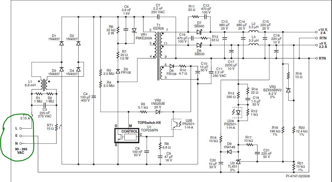
i'm trying to implement this SMPS in a design, but i'm not sure i totally understand why there is a connection to EARTH (the E in the input terminals on the left) in the schematic bellow. .
.
Can someone please help me out here? Thanks!
i'm trying to implement this SMPS in a design, but i'm not sure i totally understand why there is a connection to EARTH (the E in the input terminals on the left) in the schematic bellow. .
.
Can someone please help me out here? Thanks!
The reason the earth pin is at the input is because this particular power supply references its output voltages to it. Note that the power supply itself runs from the L and N (line and neutral) inputs, and that it's output is isolated from them. The outputs are then deliberately referenced back to the earth input line.
Some power supplies allow the output to float, others specifically reference it to something. This is one of the latter.
I have seen plenty of SMPS with inputs labeled L, N, and E/GND, yet they are designed to run on American style 240VAC (ie fed by two hot wires, both 120VAC from ground). I think more appropriate labeling would be L1 and L2, but that would confuse some people wiring in a hot and neutral.
When you consider how easy a product built with this supply could get powered with the N terminal connected to a hot line (240V circuit, incorrect cord or outlet wiring, etc.), it would almost be negligent to not tolerate that condition. By designing it such, the manufacturer reduces its liability and offers a more flexible product.
One possibility why the RTN is connected to E is to protect the isolation from ESD. That can be inconvenient for some applications. There are plenty of supplies available that float.