0
\$\begingroup\$

I'm new to the website, I found it while trying to research the problem I'm having and thought I could just ask the experts directly :)

I am a student who is trying to design a power supply circuit (DC). I've used Multisim over the past year but I'm still not completely savvy with it.

I have some criteria to meet with the question, and it was going really well until I tried to view the Oscilloscope.

Secondary output voltage needs to be 12v, the DC Output voltage should be 10v, the Peak–Peak ripple voltage must be less than 1.2v, maximum full load output current of 0.5A, Over-current protection to be active at 0.5A and regulation must be better than 10%

At first I was getting the 12V, the 10V and the <0.5A current, but suddenly something just went wrong, I didn't change anything. The DC output voltage began to climb with no signs of stopping and went way over the 10v it was sitting comfortably at.

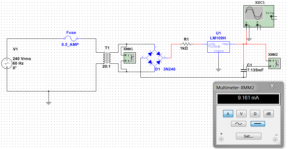
enter image description here

enter image description here

I would post more pictures but it says I don't have enough reputation points to do so yet. But the Oscilloscope was just straight and constant at zero when the voltage was consistent at 10V, and then (when the circuit did whatever it did!) the voltage started rising on XMM2 with no signs of stopping, and the Oscilloscope showed a large waveform which got smaller and smaller as the voltage increased.

I'm no expert as you can probably tell, if anyone could tell me what I'm doing wrong or how I can fix this I would appreciate it so much.

I'm sure I've connected something incorrectly or missed something out, but I've tried adding, removing and changing everything I can think of and I can't get it working.

\$\endgroup\$
4
  • \$\begingroup\$ Your connections are totally wrong. 1) Don't connect the system ground to your 240V supply. 2) Regulator IC's COMMON terminal should be grounded as you did, but this terminal should also go to the bridge rectifier's left-most common-anonde terminal --since it provides a return path. And finally, 3) Don't even try to place an ammeter (XMM2) across the output terminals. \$\endgroup\$ Commented Oct 12, 2016 at 9:03
  • \$\begingroup\$ Thank you for replying! I appreciate your advice, this is my first attempt so I didn't expect to get it right straight away :) \$\endgroup\$
    – user126396
    Commented Oct 12, 2016 at 9:07
  • \$\begingroup\$ I have removed the ground near the supply, connected the common to the return terminal and grounded it and have removed the Multimeter replacing it with a current probe. puu.sh/rGhMi/6e0b94ef68.png I have no measurement of the output DC voltage now and the peak-peak is too high. Any suggestions please? Thank you :) \$\endgroup\$
    – user126396
    Commented Oct 12, 2016 at 9:14
  • \$\begingroup\$ You've to place an electrolytic capacitor across the output terminals of bridge rectifier (e.g. 470uF). Please, first, read some tutorials about basic AC-DC conversion. Here is a good reference: homemade-circuits.com/2012/03/… \$\endgroup\$ Commented Oct 12, 2016 at 9:24

1 Answer 1

0
\$\begingroup\$

I added a potentiometer which solved the problem, thanks @Rohat for responding it's sorted now :)

\$\endgroup\$

Your Answer

By clicking “Post Your Answer”, you agree to our terms of service and acknowledge you have read our privacy policy.