13
\$\begingroup\$

I'm trying to measure current to a DC motor on an RC car I took apart. The car is powered by 3 AA batteries and seems to be made of three different boards. Two of the boards are for switches and LEDs, the other is the main one in this shot that I'm trying to measure so I can replace it with my Arduino.
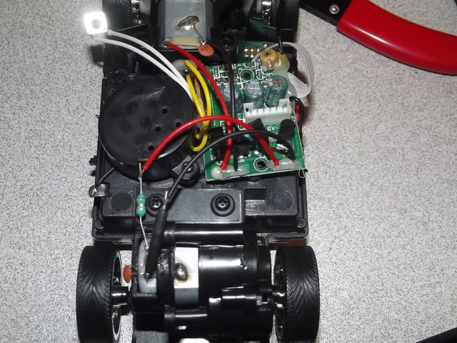
http://i.imgur.com/Ck2kO.jpg

I am trying to measure the amperage to the motor, as well as that motor in the back of that shot. I have tried using my multimeter on 20mA, 200mA, and 10A with no sensible reading and it always stalls the RC car.

Shouldn't I be able to get a reasonable result?

Edit: All the pictures I have of it are in this page

I've tried connecting on the motor directly and on the wires leading to it both before and after that capacitor.

Edit: Thanks again for the help everyone. I'm going to give it another go soon and post some pictures of the configuration once I get it going

\$\endgroup\$
3
  • 1
    \$\begingroup\$ I guess details of where exactly you connect the ampermeter are important. \$\endgroup\$
    – sharptooth
    Commented Feb 14, 2012 at 8:46
  • \$\begingroup\$ Updated with position of where I have tested \$\endgroup\$ Commented Feb 14, 2012 at 9:02
  • \$\begingroup\$ +1 for the photos; make some with the amperometer connected, to show us how you do that \$\endgroup\$
    – clabacchio
    Commented Feb 14, 2012 at 12:23

3 Answers 3

12
\$\begingroup\$

From the photos you provide it is clear that you try to measure current without disconnecting the motor by connecting the ampermeter in parallel to the motor.

An ampermeter will have very low resistance (a perfect ampermeter would have zero resistance so that it doesn't affect the measured current). So by doing that you short the motor (well, actually you short the circuit that drives the motor, but it doesn't matter). This of course stalls the car and btw puts extra load on the driving circuit which can damage it.

You have to connect the ampermeter in series with the motor - disconnect either of the wires and connect the ampermeter somehow like this:

---wire--ampermeter--motor--otherWire
\$\endgroup\$
2
  • 3
    \$\begingroup\$ Also there's a chance that the measurement activated fuses in the amperemeter. \$\endgroup\$
    – AndrejaKo
    Commented Feb 14, 2012 at 13:03
  • \$\begingroup\$ Thank you! I'll post pictures with my attempts when I am home from work \$\endgroup\$ Commented Feb 14, 2012 at 19:49
8
\$\begingroup\$

As an alternative to what sharptooth said:

If that's a resistor in series to the motor (left bottom; green device, probably blue, gray, gold rings = 6.8 Ohms; not sure; could also be just an inductor for radio interference suppression) you can measure the voltage U accros that resistor R. So you don't have to open any connection.

The current is I = U/R (Ohms law).

This measurement will tamper the actual current less than inserting an ampere meter, because resistance of todays voltage meters is so high (probably some 100KOhms-MOhms) that it can be neglected whereas the resistance of ampere meters (maybe 0.1-1 Ohm; depending on the range) still is not low enough when measuring "large" currents.

\$\endgroup\$
2
  • \$\begingroup\$ Voltmeter resistance should also be taken into account. \$\endgroup\$
    – sharptooth
    Commented Feb 14, 2012 at 10:18
  • 5
    \$\begingroup\$ @sharptooth: probably doesn't matter at all, because it will be in the kOhm-MOhm range; parallel to 6.8 Ohms can be completely neglected. \$\endgroup\$
    – Curd
    Commented Feb 14, 2012 at 10:21
8
\$\begingroup\$

Instead of trying to measure motor current while it's in the circuit, I would measure the motor by itself. That is easier to do and let's you find out what the limits are, not just what the circuit happens to drive it at.

Disconnect the motor and run it from a 4.5V power supply, which is about what to expect from three fresh AA batteries in series. If you have a power supply that can show current, then that will be good enough. I expect the current to be at least a few 100 mA, which most power supplies will show with reasonable resolution. If not, put your ammeter in series with the motor to measure the current. Start with the 1A scale.

There are two measurements you should make to get a feeling for the motor. The first is with the motor running with no load. Let the wheels freely rotate. The motor will draw the minimum current this way. Then try it for a short time with the wheels held so that nothing rotates. The motor will draw the maximum current this way. This is also known as the "stall current", which you would see in its datasheet if you had one. Let the wheels rotate just a little to get the stall current at different motor positions. Brushed DC motors can have a bit different current draw over a revolution depending on what combination of coils are being activated by the brushes.

Once you have the min and max current, you can design your drive circuit around it. Since you probably want variable drive and bi-directional, you want to drive the motor with a H bridge controlled by PWM from the micro. I don't know what capabilities the arduino has, but there are real micros out there with PWM hardware specifically meant to drive such H bridges. These make direction changing easy, handle break before made, etc.

\$\endgroup\$
1
  • \$\begingroup\$ Thanks. Im trying to discover as much as possible before I disconnect anything, but I will do that as soon as I can and post back. \$\endgroup\$ Commented Feb 14, 2012 at 23:27

Your Answer

By clicking “Post Your Answer”, you agree to our terms of service and acknowledge you have read our privacy policy.

Not the answer you're looking for? Browse other questions tagged or ask your own question.