16
\$\begingroup\$

Is there a low cost and reliable way to identify a USB charging port?

I plan to charge a device via the USB port. The USB Battery Charging Specification 1.1 allows 1.5A current draw when connected to a Dedicated Charging Port (DCP) and 500mA when connected to a Charging Downstream Port (CDP). A DCP is typically a wall wart and a CDP is typically a computer. As far as I understand, a DCP is identified by shorted D+ and D-lines, a CDP id identified by D+ and D- being pulled to ground through 15k resistors.

It seems like identifying these ports takes quite a bit of extra hardware. I could probably bias the D+ line and connect D- to an ADC input to look for a DCP. And some similar arrangement to check for a CDP. I assume I would also need to disconnect the bias and ADC when done to not interfere with USB communication. The USB pads on my mcu are not 5V tolerant and are dedicated USB pads (I'm using an LPC1343).

Identifying the non-standard Apple and Sony chargers would be an added bonus, but not critical.

Does anyone see a simpler or better way to do this?
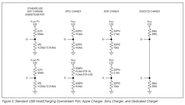
USB charge ports

From this datasheet

\$\endgroup\$
1
  • 1
    \$\begingroup\$ "USB Battery Charging Specification 1.1 allows 1.5A current draw when connected to a Dedicated Charging Port (DCP)" I don't think that's correct, though the spec is very hard to read. From what I understand, you draw increasing amounts of current until the voltage starts to collapse, and then you can't draw more than that. Different DCPs can supply different amounts of current, in other words. \$\endgroup\$
    – endolith
    Commented Jun 8, 2016 at 17:22

3 Answers 3

3
\$\begingroup\$

Although I don't have direct experience with this, from what I've read, IC's that perform this function usually sample the D+/D- lines on application of power with some sink on the D+/D- to detect the charger type, and disconnect their detection logic once a determination has been made of the connected source, AC adapter or USB port. More information is available from a TI app note here.

I sure from my previous part searches that some battery charger IC's have built in charger type detection, but I couldn't find an example part when searching just now.

There's the MAX14578 which also does the job, but it may not fit your criteria of low cost.

\$\endgroup\$
4
  • \$\begingroup\$ Thanks. Using a dedicated detector chip may be the best approach all things considered. The Maxim chip has some ESD protection so I can save some cost there. \$\endgroup\$
    – morten
    Commented Feb 20, 2012 at 9:11
  • \$\begingroup\$ or you can use my answer which lists two of these chips. \$\endgroup\$ Commented Jan 9, 2017 at 14:09
  • 1
    \$\begingroup\$ Also the Texas Instruments BQ24392 chip will detect a DCP, CDP, or SDP and tell you which type of port is detected. \$\endgroup\$
    – user4574
    Commented Feb 26, 2018 at 18:30
  • \$\begingroup\$ The BQ24392, FSA832, and MAX1463x are clones or near-clones. \$\endgroup\$
    – endolith
    Commented Mar 18, 2021 at 21:47
1
\$\begingroup\$

You can use one of the ICs created for this purpose, for example:

For example:

TPS2511 USB Dedicated Charging Port Controller and Current Limiting Power Switch features:

* Supports a USB DCP Shorting D+ Line to D– Line
* Supports a USB DCP Applying 2 V on D+ Line and 2.7 V on D– Line (or a USB DCP Applying 2.7 V on D+ Line and 2 V on D– Line)
* Supports a USB DCP Applying 1.2 V on D+ and D– Lines

Where USB DCP is the standard for USB Dedicated Charging Port controllers and power switching, unfortunately each mobile phone company has its own way to implement this "standard". This is the reason why these ICs exist, to make USB charging ports comply with the various "standards".

\$\endgroup\$
3
  • 1
    \$\begingroup\$ Simple link-based answers run the risk of deletion. Please elaborate on how these IC's can help the OP solve his/her problem. If the links go down, this simple answer has no meaning. Also, please answer ALL of the OP's questions so your answer is complete. \$\endgroup\$
    – user105652
    Commented Jul 2, 2016 at 4:03
  • \$\begingroup\$ These ICs were created to solve exactly the problem OP presents. The answer states thus "... created for this purpose ..." what more would I say? I don't really know how these ICs are made inside, so I cannot elaborate on the inner workings of proprietary ICs, only mention their names. Completely unjust vote down imho. \$\endgroup\$ Commented Jul 4, 2016 at 4:20
  • 1
    \$\begingroup\$ @Evgeny You can at least describe the features of these ICs. Like, summarize what's in the description of the datasheets. Or mention typical cost / area / pin budget. \$\endgroup\$
    – florisla
    Commented Oct 25, 2016 at 13:32
-1
\$\begingroup\$

I am not sure why you want to know what kind of port device is using but maybe it would be sufficient to check voltage drop around 500 [mA]. If voltage drops or cuts off when exceeding 0.5 [A] then it is probably standard port. If device is USB powered then my method require some kind of additional short-term power source and both current and voltage measurement. However the simplest solution is to use external switch left for user to operate.

\$\endgroup\$
3
  • 2
    \$\begingroup\$ When the user connects a USB cable I need to know how much current I am allowed to draw. The brute force method of increasing load until the other end dies is not well behaved and I'd rather avoid it. \$\endgroup\$
    – morten
    Commented Feb 20, 2012 at 9:06
  • \$\begingroup\$ Over-current protection is mandatory according to USB specification, every source should be prepared to withstand short-circuit. I do not see harm in my method, but it's true that probing data lines is much better practise. \$\endgroup\$
    – Matt Kucia
    Commented Feb 20, 2012 at 12:44
  • 1
    \$\begingroup\$ @morten Isn't that exactly how the USB Battery Charging spec works? "For a dedicated charger or USB charger, the current limit is determined by loading the adapter. When the adapter’s output voltage starts to collapse, it is an indication that the current limit of the device is reached." \$\endgroup\$
    – endolith
    Commented Jun 8, 2016 at 17:20

Your Answer

By clicking “Post Your Answer”, you agree to our terms of service and acknowledge you have read our privacy policy.

Not the answer you're looking for? Browse other questions tagged or ask your own question.