3
\$\begingroup\$

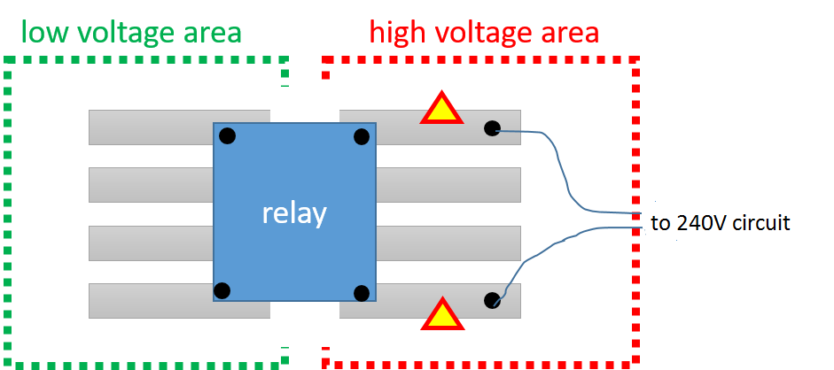
I need to use a relay to control a 240V circuit via a low voltage (5V) one:

enter image description here

Beside making sure that the "high voltage area" is correctly insulated from users one point which worries me is whether the strips marked with a triangle are designed to be used with mains voltage. The expected current will be about 2A.

Which current are typically stripboard designed for? I am looking for an order of magnitude (100mA vs 1A vs 10A)

\$\endgroup\$
6
  • 1
    \$\begingroup\$ If all you want is an order of magnitude, one possible approach would be to measure the width of the trace, speculate how thick it is (maybe go with 1/2oz?) and go to a trace resistance calculator. From that you can derive how much current you can put through it. \$\endgroup\$
    – Wesley Lee
    Commented Nov 22, 2016 at 10:43
  • \$\begingroup\$ @DmitryGrigoryev: I saw that question (agreed, i should have mentioned that) -- my question is specifically on the resistance to current of strips, the other answers were about general safety or distance between strips \$\endgroup\$
    – WoJ
    Commented Nov 22, 2016 at 18:10
  • 2
    \$\begingroup\$ Can I assume this diagram is for illustration purposes only? Because otherwise you're going to turn on the relay and the breaker will trip (hopefully) if the mains plug is plugged in. \$\endgroup\$ Commented Nov 22, 2016 at 19:51
  • \$\begingroup\$ @immibis: yes, I realized after having posted that the right side does not make sense. It will be a real circuit with mains and a lamp or something similar :) \$\endgroup\$
    – WoJ
    Commented Nov 22, 2016 at 20:09
  • \$\begingroup\$ @WoJ -- even if it is for illustration purposes, would you mind substituting the image with a correct one please? It'll only cost you a couple minutes.. You never know who will see this and try to copy it, idk.. just in case. \$\endgroup\$
    – Wesley Lee
    Commented Nov 22, 2016 at 21:09

5 Answers 5

11
\$\begingroup\$

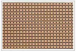
This is the stuff I presume you mean: -

enter image description here

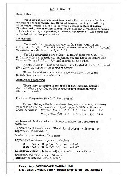
In the UK it used to be called veroboard and here is a specification issued by the manufacturer: -

enter image description here

Note that the Ministry of defence recommended maximum voltage is 500 volts. 240V AC peaks at about 340 volts but I'd be concerned about using adjacent tracks for mains voltage.

Details taken from here.

I would urge you to contact the supplier of your strip board to see what they say. Also, given the sort of working environments that strip/vero board is used and the potential for contamination landing between tracks I would be very cautious about using it at 240 volts.

\$\endgroup\$
1
  • 7
    \$\begingroup\$ I totally agree. The clearance between the strips is just 0.254mm, but to my knowledge, >0.56mm is recommended for 250Veff. The three gaps in the picture are enough in sum, but I don't like the (unused) copper stripes between them. There are also strip boards with copper on every second row only out there. I'd use this stuff. \$\endgroup\$
    – sweber
    Commented Nov 22, 2016 at 12:20
3
\$\begingroup\$

Be careful. It is a good idea to scrape the adjacent tracks away (maybe with a rotary tool).

There are phenolic paper-based boards, and also epoxy-based boards. phenolic boards tend to absorb humidity and this could get nasty.

For 230V applications I would always spend the extra buck and get an epoxy-based board.

\$\endgroup\$
0
\$\begingroup\$

Since the scan in Andy's answer has already answered your question (no. It's not OK, neither from a security/clearance point of view, nor from a heating / resistance POV for >5A) to use stripboard, I'd recommend you'd use one of the hundreds of "trace width calculators" out there to find the minimum trace width necessary for your currents at a given copper thickness (ie. 35µm, usually).

Add a solid bit of tolerance for the fact that you've got low-crossection regions whenever there's a hole in your stripboard "line".

I'd advise you to not use stripboard, especially not the paper kind. And when you're already getting epoxy stripboard, you might as well just quickly click together a custom PCB which does exactly what you need, comes with an isolating lacquer (so you won't instantly cause a fire if a paperclip falls onto the trace – and you reduce the risk of death by reducing the area of exposed grid voltage) and has no holes where you don't need them, nor lines where there should be clearance. Getting such PCBs manufactured is very cheap nowadays.

Many hobbyists use Eagle, and I prefer KiCAD, to design such boards and generate the files needed to order a custom PCB.

This will make adding a lot of features really easy: For example, adding a fuse holder in-line to the design would then become trivial. Or, integrating whatever grid voltage circuitry you need (a resistor + LED to indicate your relay is on, for example, would be extremely easy to add). Also note that Eagle, KiCAD and others support design rule checks – and if you define your grid side connections to need a clearance of eg. 1.5mm (refer to proper clearance tables, they are standardized for different voltages), then your design tool can check you never accidentally put two traces too close together. Neat!

All in all, as soon as you start playing with grid voltage, five rules apply:

  1. be careful
  2. be extra careful
  3. apply care when designing things
  4. mind that you should be careful when building stuff
  5. watch yourself that you're careful when operating gizmos.

And under rule 1-3, making a proper plan of how your traces should run is practically implied. And when you do make a plan, you're basically designing a PCB.

Thus, in my humble opinion:

When dealing with grid voltage, there's no place for stripboard. Safety deserves enough attention to force you to design a PCB from scratch, anyway.

\$\endgroup\$
0
\$\begingroup\$

If you want a generic, order-of-magnitude answer, it would be: 1A

I would also completely remove strips on either side of any mains-voltage.

Even better would be to use an inexpensive relay "break-out board" which will be more likely to have the proper trace width, thickness and spacing.

\$\endgroup\$
0
\$\begingroup\$

Normally clean dry smooth parallel conducting surfaces have a breakdown voltage of 3kV/mm and sharp edges 1kV/mm. Flux and dust or moisture can reduce this on PCB's so they generally have a routed 1.5 to 2mm" air slot for Opto Isolators or partitoning the board from Hi-V , since inductive grid load switches can exceed 3kV known as power line transients or PLT.

it can be done with care with an fuse inline or power-strip breaker.

With no fuse and an arc occurred. it would explode and melt a crater big enough to poke a pen thru it. poof , with enough energy to melt fat screw driver blades in milliseconds.

No problem. Good way to learn how the grid works.

\$\endgroup\$

Not the answer you're looking for? Browse other questions tagged or ask your own question.