5
\$\begingroup\$

enter image description here

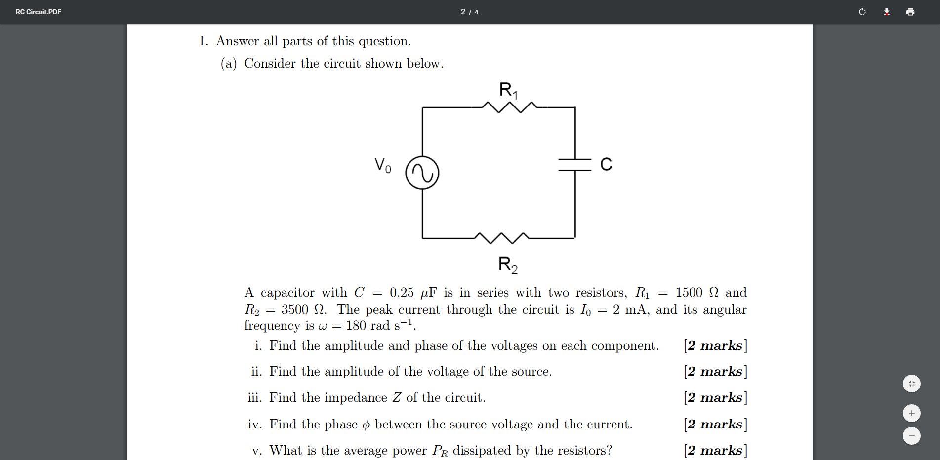
OK so here it is. Now I am not asking anyone to do this for me, I am just confused because my professor did this in class and I just cant make sense of it. I repeat, this is not a homework question, I am legitimately trying to understand this.

Ok so the first part is straight forward I think. The phase of the resistors are 0degrees and the capacitor has a -90 degree phase shift between the voltage across it and the current through it

The voltages of the resistances are 3V and 7V and the capacitor has a complex reactance given by 1/jwc which gives -22222.2j ohms and a voltage of -44.4jV

Now the next part is what confuses me. As I understand it to calculate the voltage of the source I should add the voltages in complex quadrature. That gives me 45.5V however my professor simply subtracted |10-44.4| to give 34.4V I don't understand this at all. How can he add the two together when one is imaginary? I know that Xl (i.e. 1/wc) gives the magnitude of the reactance however the phases for each component are different so I don't see how you can just add them.

Then for the third part he again simply added the impedances together to get 27.2kohms, although I suspect this may have been a simply error copying from the notes.

Then for the last part (v) I understood that to get the average power dissipated I would need to take the rms current and use P = I^2(R) however he simply used the value of the peak current and the voltages calculated earlier on P=VI

Can someone please help me, I thought I understood this stuff but this has really confused me. Even telling me what it is I am misunderstanding without any great depth would be a huge help, I can then go and read up on it myself.

\$\endgroup\$
1
  • 7
    \$\begingroup\$ I think you need a prof who understands circuit analysis! For the second and third parts, you seem to be doing this right, and the prof is wrong IMO - or at least, you misunderstood what he said, or your notes are wrong. \$\endgroup\$
    – alephzero
    Commented Dec 11, 2016 at 23:37

2 Answers 2

1
\$\begingroup\$

You are right in everything but, in the impedance, you forgot the phase:

$$Z_t=(5000-22.222Kj)\Omega = (22.777K\angle-77.32^{\circ} )[ \Omega ]$$

\$\endgroup\$
1
  • 1
    \$\begingroup\$ Yes, and the average power dissipated in the resistors is 10mW (V=10V multiplied by I=2mA, divided by 2 because both the R1+R2 voltage drop and current flowing through them are peak values). \$\endgroup\$
    – Eric Best
    Commented Mar 23, 2017 at 1:02
0
\$\begingroup\$

Deal with everything in equations and you will see the mistake..

\$ V_0=I_0(R_1+R_2+Z_C) \$

Where \$ Z_C \$ is the Complex impedance given by \$ Z_C=1/jwC\$

As you have already calculated \$ Z_C= -22222.2j\$

Substituting it in the first equation with values of R gives,

\$ V_0= 2m(5000-22222.2j)\$

If you are to represent \$ (5000-22222.2j)\$ in polar form

it would be \$22777.75\angle-77.31^0 \$

Substituting in above equation

\$ V_0=2m*22.77K \angle-77.31^0 \$

which would give

\$ V_0=45.54V\angle-77.31^0 \$

Since its a series circuit. The current through all the elements is the same.

i.e \$ I_0=2m\angle 0^0 \$

Now as far as the individual drops are concerned for the Resistors and Caps again we do the same thing

\$V_{R1}=I_0*R_1 \$

\$V_{R2}=I_0*R_2 \$

\$V_{C}=I_0*Z_C \$

Getting

\$V_{R1}=3V\angle 0^0 \$

\$V_{R2}=7V\angle 0^0 \$

\$V_{C}=44.44V\angle -90^0 \$

You can easily remove the confusion if u always represent the Voltages and currents finally in Polar form.

\$\endgroup\$

Not the answer you're looking for? Browse other questions tagged or ask your own question.