1
\$\begingroup\$

First of all, I'm sorry if this question turns out as a duplicate (since I absolutely have no idea about the keyword I should used).

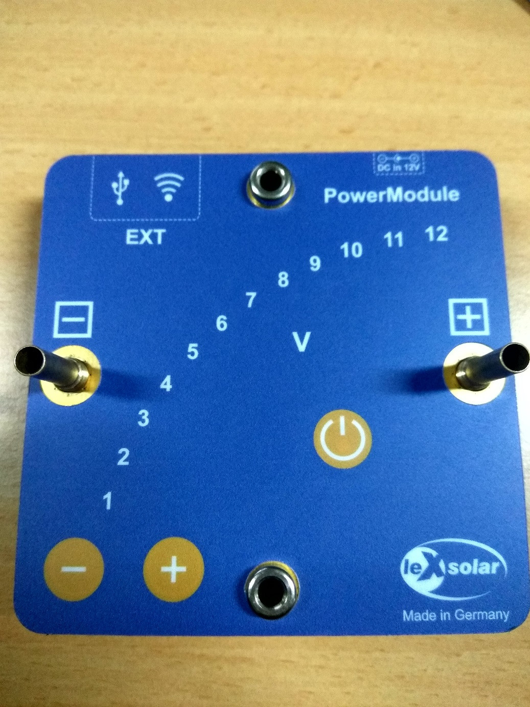
I am trying to recreate a power supply (DC) which can have multiple output level. My model is Lex Solar Power Module (sadly its broken now, thus why I am trying to create my own)

enter image description here

Description about the module :
It supplied with 12V 2A adaptor, and able to deliver single 1-12V output with 0.5V increment/decrement based on the input ('+' or '-').
At first, I though it was only analog, but turns out its using STM32 as main controller.

So, my question is, what should I look for? What is the technical terms of this type of power supply, and perhaps along with an example of IC used.

EDIT------------
I forgot to mention one thing about the module characteristics, when constant load is used (i.e. 1K resistor), when the output is 1V, the current is 1mA, so does when the output is 5,6,7,8 V, the current is 5mA, 6mA, 7mA and 8mA. In short, current raise as the voltage raise.

If there any disambiguation about my question please ask, I will try to fix it. Thanks

\$\endgroup\$
14
  • \$\begingroup\$ By 'multiple output level' do you mean 'single adjustable output'? \$\endgroup\$
    – Wesley Lee
    Commented Dec 14, 2016 at 9:16
  • \$\begingroup\$ Yes. It only has one output, but the voltage can be changed using touch capacitive sensors as shown on screen ('+' and '-') which change the output by + or - 0.5V \$\endgroup\$
    – duck
    Commented Dec 14, 2016 at 9:19
  • \$\begingroup\$ Note that there are ready-build modules available which do a similar job, for example: ebay.nl/itm/… Although it is possible to make an exact functional duplicate of the device you have it will require a lot of work and knowledge. \$\endgroup\$ Commented Dec 14, 2016 at 9:34
  • \$\begingroup\$ @FakeMoustache thanks for the reference, it's kind of open up my mind. Actually I want to learn further about electronics by trying to make this. \$\endgroup\$
    – duck
    Commented Dec 14, 2016 at 10:01
  • \$\begingroup\$ want to learn further about electronics Excellent !! But if you have little experience then digital control and a switched converter might be a bit of a challenge. There are many small things you need to know, which are often learned by experience from a much simpler project. What you could do is find a power supply / lab supply project on the internet. There are many and at various levels. Pick one you think would be doable for you. Trying to make an all-singing-dancing supply as a first project might end in tears :-( better avoid that. My lab supply is also a the 3rd I build ;-). \$\endgroup\$ Commented Dec 14, 2016 at 10:13

1 Answer 1

3
\$\begingroup\$

It's a buck regulator. The MCU is most likely used for handling the interface and supplying a reference voltage to the analog section of the device.

There are literally hundreds if not thousands of buck regulator devices; pick a vendor and look at their lineup. It is also not terribly difficult to build one from scratch using only discretes and MSI chips.

\$\endgroup\$
4
  • \$\begingroup\$ Thanks @Ignacio, I've read the link you gave, so far, here is my analysis about the concept of the original module (please correct me if I'm wrong): Input will change pwm level generates by MCU (whether its '+' or '-') at constant value so that the result from buck regulator is up or down by 0.5V? \$\endgroup\$
    – duck
    Commented Dec 14, 2016 at 9:59
  • \$\begingroup\$ @dpw that's reading a bit much into it. Ignacio just said that the MCU is probably used to generate a reference – and I'd agree with that assumption. So maybe the MCU is used to generate something between 0-3V as reference, depending on what buttons you've pressed, and then there's circuitry that compares the output of the buck regulator to multiple of that, and adjusts the buck regulator's operation accordingly. Whether anything of that happens with a PWM is details \$\endgroup\$ Commented Dec 14, 2016 at 10:13
  • \$\begingroup\$ @IgnacioVazquez-Abrams after re-read your explanation about MCU, I think that my initial guess was wrong. Can you explain more about "the MCU is most likely used to ... and supplying a reference voltage to the analog section of the device". What "device" is it exactly? is it some kind of feedback using DAC? \$\endgroup\$
    – duck
    Commented Dec 27, 2016 at 4:54
  • \$\begingroup\$ @dpw: No, it's probably just a regulator that uses an op amp or two to determine the error between the reference and the output. \$\endgroup\$ Commented Dec 27, 2016 at 6:27

Your Answer

By clicking “Post Your Answer”, you agree to our terms of service and acknowledge you have read our privacy policy.

Not the answer you're looking for? Browse other questions tagged or ask your own question.