1
\$\begingroup\$

I am power a Bluetooth module (referenced as BLE) operating at 3.3v. The module has a microcontroller inside and we want to keep the RTC working all time for scheduling, which means in case if the main power source goes down, the module will keep running on the battery.

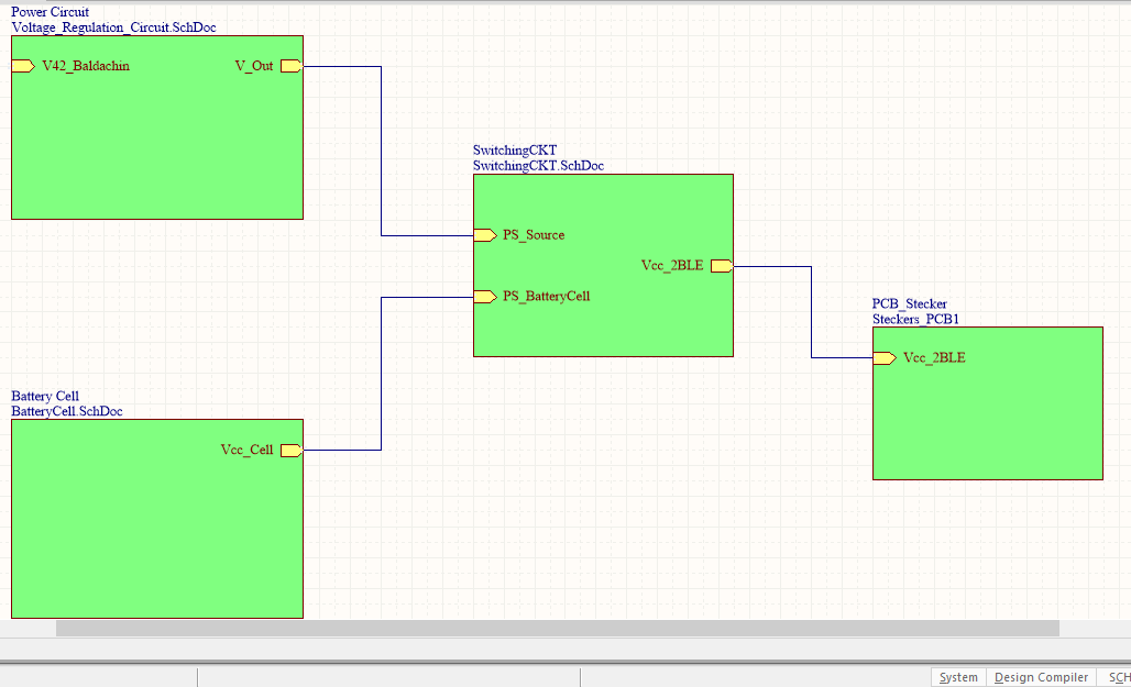
As you can notice in this overall design, two sources to the left (mainly voltage from source and the Battery Cell c2032. The two are fed into a circuit that selects the battery in case of power absence.

I would like to inquire if there is any suggested circuit for that to switch immediately in order to to keep the timer working.

enter image description here

Waiting for your suggestions. Thank you.

\$\endgroup\$
1

1 Answer 1

4
\$\begingroup\$

Dual-supply is a very common problem, and thus, you might simply have a look at the circuitry that selects power sources on commercial devices to get inspiration.

Note that microcontrollers with RTC often have a separate V_bat pin that allows a buffer coin cell to be used to run the RTC when main power is down. I recommend checking that you don't have that prior to considering working on a power switch.

You can usually build such power selection circuitry out of a few discrete semiconductors and resistors – however, considering you sound like you're designing for manufacture, it's probably easier AND more cost-efficient to use a specialized IC for that. Every major IC manufacturer (TI, ST, Maxim, NXP/Qualcomm, Linear, ON Semi, …) has a "power management" category.

What I've used is an LTC4412 – the datasheet has good example application circuits. I don't know if it's for 3.3V, but you should check the datasheet to learn what kind of device you're looking for. You'd probably want the LTC4411, which includes the switch in the IC itself, and is about USD1.90 in quantities of 100.

Note that you'll definitely need to know whether you're running off battery or grid power in your software – a coin cell really has not that much energy, and you'd want to avoid doing too much communication in order to make it last as long as possible.

\$\endgroup\$
2
  • \$\begingroup\$ I tried to have this one if you can let me know your feedback: Connecting both the Source and the Cell to SD103ATW-7-F (SCHOTTKY BARRIER DIODE ARRAY) and then connected the output? Would that be working properly? \$\endgroup\$ Commented Dec 21, 2016 at 14:06
  • \$\begingroup\$ nope, can't give you feedback to a complex question in a comment, sorry! Better ask this as a new question, draw a schematic, describe your observations & measurement \$\endgroup\$ Commented Dec 21, 2016 at 14:22

Your Answer

By clicking “Post Your Answer”, you agree to our terms of service and acknowledge you have read our privacy policy.

Not the answer you're looking for? Browse other questions tagged or ask your own question.