I'm an hobbist, so the reason of the silly question.
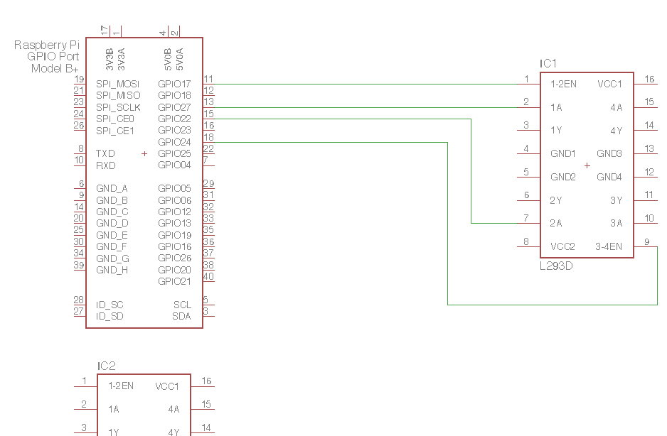
So I'm drawing with Eagle ( express ) a schematic for a DC motor driver with raspberry. I'm planning to use 2 L293D to drive four motors + another chip to drive a stepper. Anyway my drawing is at this point:
 since I got that adding all the component would create a big unreadable mess. How can make this more readable? Ideally the GPIO port on the left should be divided in smaller parts, but without loosing the information that pins are belonging to the same connector. How to do it?
1 Answer
Eagle assigns a name to each network. As soon you connect two pins, there's a name N$nnn assigned automatically and used for any connections of further pins (and when you join two networks, eagle asks which name to use for both from thereon.)
You are allowed to cut the wires between network segments.
Again: You are allowed to cut the wires between network segments.
The wires keep being connected because they share the same network name.
That means you can cut wires, then add drawing elements to show a reader those wires should be connected. The parts from the dports library are intended for that purpose. But you can also simply use the label command (or icon). Another thing that comes in handy is you are allowed to rename networks. So, use the name command (or icon) to assign a nice name as /EN1 to a network.
You can also rename two network segments which have never been connected by a wire and use the dialog box to connect the two but that is a bit error prone. You may end up accidentally connecting all wires to one single network if you aren't careful. You need this technique for connecting wires on different sheets though.
For buses, it's common practice to let the single wires of a network end blind at all sides and use a bus bar to connect the sides visually.
-
\$\begingroup\$ Is the dport library one of the standard Eagle libraries or one of your own? I don't see it in my Eagle 7.7.0 installation. \$\endgroup\$ Commented Jan 14, 2017 at 10:07
-
\$\begingroup\$ Thank you, so for completeness, what is the best practice for my case? Just show the label on each IC/port or a mixed approach? \$\endgroup\$ Commented Jan 14, 2017 at 11:24
-
\$\begingroup\$ @Roger Rowland: cadsoft.io/resources/libraries/?query=dports \$\endgroup\$– JankaCommented Jan 14, 2017 at 12:09
-
\$\begingroup\$ @Felice Pollano: The general idea is people don't like to follow a maze of wires. For a few connections as you have, I would simply use dports. If it was say 8 parallel wires, one could think of using labels and a bus bar instead. Again, that is purely a visual element. Bus bars do nothing. I usually mix all three ways. \$\endgroup\$– JankaCommented Jan 14, 2017 at 12:15
-
\$\begingroup\$ @Janka Ah, ok, one of Bob Starr's, thanks for the link. \$\endgroup\$ Commented Jan 14, 2017 at 13:02
