My ham radio has a speaker output rated at 2W, 8 ohms. I want to increase the power to feed a 30W speaker, which is also 8 ohms. How can I connect an amplifier to this speaker output? The amp I'm looking at now is a Kinter MA-170. Its output is good, at 18W, 4-16 ohms. But the input impedance is 47K ohms, and I don't know if it can handle the speaker-level output. There is no line-level output available on this radio.
-
\$\begingroup\$ How secure are you about the idea of galvanically connecting up these two devices? (I wouldn't feel safe about recommending it without a lot of testing first, if both are mains-powered devices.) \$\endgroup\$– jonkCommented Mar 4, 2017 at 7:49
-
\$\begingroup\$ Both devices would be powered by a 12V car battery. \$\endgroup\$– Elliott BCommented Mar 4, 2017 at 8:12
-
\$\begingroup\$ Ah. Thanks. I've already posted out an answer, though, before reading that detail. Have you considered the idea of a resistor divider followed by a non-polar series capacitor? You might try that, as well, in this case. Do you intend on removing the existing speaker? \$\endgroup\$– jonkCommented Mar 4, 2017 at 8:16
2 Answers
I haven't ever considered using them and don't know much about them, but there seems to be any number of "speaker level to line level output converters" you can google up. At only 2 W output, a few of the cheap ones may work. But I honestly don't know what they look like, inside. And without having tried any, either, I can't recommend anything specific. But it's a direction to consider, I suppose. If both your ham radio and your expected amplifier at AC-mains powered, I would be worried about the possibility of getting a hot line tied to a ground when using one of them. So you probably should do some of your own basic testing before risking either system, if you decide to go this route.
A galvanic connection, using a resistor divider followed by a non-polar capacitor to the RCA inputs of the new amplifier system might work okay if you can be sure you've safely dealt with mains grounding issues of each device (and may not care much about "hum".) The signal will get across pretty well that way and you can adjust things for about a 4:1 step down ratio without much difficulty (the reason for that is that higher of the two consumer line input specifications would shift the peak \$5.7\:\textrm{V}\$ to a peak of about \$1.4\:\textrm{V}\$.)
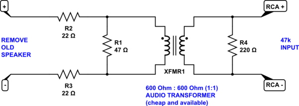
I can't recommend a galvanic connection since I don't know the details of your proposed situation. The following is safer, though it won't have a uniform band-pass response over a wide range of frequencies. But it probably will do well enough for ham radio:

simulate this circuit – Schematic created using CircuitLab
If you are interested in line level information, you can check out this Wiki page on the topic. In your case, as I said before I'd probably look for about a 4:1 reduction of the signal.
The above circuit is an approach, but it's not a completed design. Audio transformers for specialized needs are rather expensive and/or require some work with an E-core transformer and some winding work. Jensen makes a really expensive (and I'm sure "nice") 4:1 audio transformer. But these are more than $60 each. And I'm too cheap for that. So that's part of why I'm instead recommending that you try out a cheap 1:1 audio isolation transformer (like from here) and use resistors to do the rest of the work. You can adjust \$R_1\$ and/or \$R_4\$ to get the transfer ratio about where you want it. Those values are just "shoot from the hip" from me, for now. (As I said, I think you want about 4:1.) The load on your radio will be lighter than with the speaker. But if your ham radio's audio amplifier section is transistor-based then I think it will be just fine. (If not, there will be a transformer involved and it may require better matching than I suggested.)
Keep in mind I'm just a hobbyist. I have some of these transformers laying about and I'd probably start with one of those and play. Mainly, I'd want isolation in this application. Just so I wouldn't worry as much.
-
\$\begingroup\$ Thanks! I should have mentioned sooner, this is all powered by 12VDC. Those "LOC" devices seem like the perfect thing, and some have adjustable gain. And for only $10, building my own would probably cost just as much. But they are all designed for much louder inputs, I wonder if they will sound okay with just 2W. \$\endgroup\$ Commented Mar 4, 2017 at 9:03
-
\$\begingroup\$ @elliottb they are cheap enough to try out. Get one designed for a power close to yours. They will attenuate more, I suppose, if for higher power systems. But you will have two volume controls to make it up. Worth trying. \$\endgroup\$– jonkCommented Mar 4, 2017 at 9:11
2watts at 8 ohms, using P = Vrms^2/R, becomes 2 = Vrms*Vrms/8, or Vrms = 4volts.
Does the amplifier not have a volume control?
If so, turn the volume control to minimum, and connect up the amplifier to the 2 watt speaker coil
-
\$\begingroup\$ Yes the radio has a volume control. I understand your calculation of 4V, but how do we know the proper input voltage for the Kinter amp? \$\endgroup\$ Commented Mar 4, 2017 at 7:23
-
\$\begingroup\$ @ElliottB you can find that information here: en.wikipedia.org/wiki/Line_level \$\endgroup\$– jonkCommented Mar 4, 2017 at 7:27
