2
\$\begingroup\$

I'm working on a photoresistor array with my arduino, and I'm having a little trouble getting stable readings.

I'm driving 7 rows one at a time with Arduino's digitalWrite(pin,HIGH) command and floating the other outputs with pinMode(pin,INPUT); Problem is, I got NO READING from my analogRead() voltage dividers unless the column is hooked up to my ohmmeter. Whats up with that?

Only the column connected to my ohmmeter outputs anything at all, all the other columns read zero. Whats in my ohmmeter that suddenly makes that sensor work?
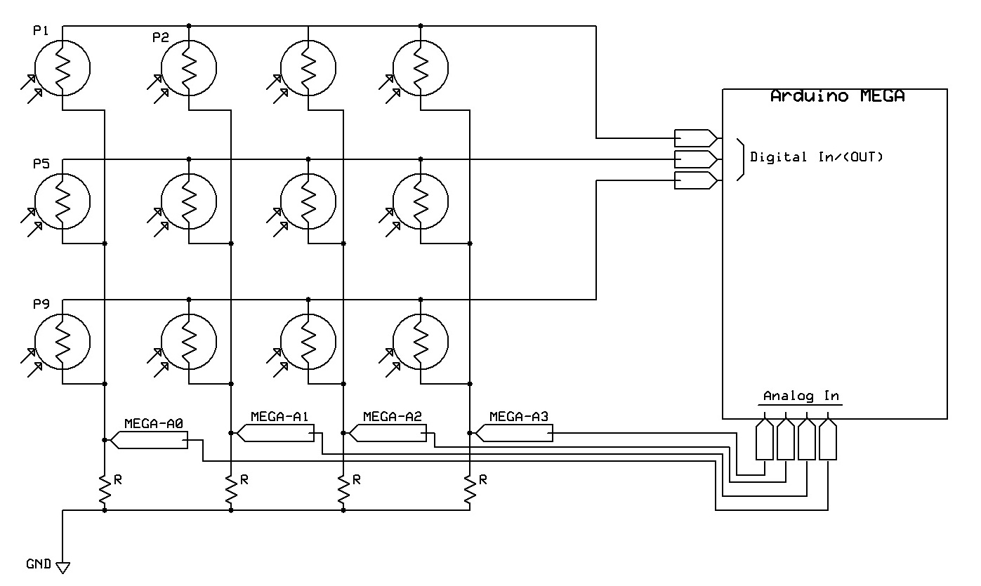
Schematic with a LDR matrix

So if I connect my Ohm-meter to the positive rail of P1 and to MEGA Analog 0 (A0) connection, suddenly the whole column gets readings! Otherwise, zeros everywhere.

void readArray() 
{ 
  for(int i=0; i < ROWS; i++)
  { 
    for(int k=0; k<ROWS; k++)
    { 
      pinMode(rowPins[k], INPUT); 
    } 

    pinMode(rowPins[i],OUTPUT); 
    digitalWrite(rowPins[i],HIGH); 
    delay(250); 

    for(int j=0; j < COLS; j++) 
    { 
      holdVals[i][j] = analogRead(j); 
      Serial.println(holdVals[i][j]); 
    } 

    digitalWrite(rowPins[i],LOW); 
  } 
}
\$\endgroup\$
3
  • \$\begingroup\$ (1) What are the values of R? (2) I would suggest adding capacitors from analog input to ground (in parallel with each R). That should decrease the output impedance that the A/D sees. \$\endgroup\$ Commented Apr 1, 2012 at 5:38
  • \$\begingroup\$ Check out my question here. I had the same problem with matrixed keypad driving. \$\endgroup\$ Commented Apr 1, 2012 at 7:38
  • \$\begingroup\$ R values are all 10k Ohm, my photoresistors have a log response from 2k-12k Ohm. @NickAlexeev I'll play with sprinkling some caps on my breadboard version when I'm back in the lab 0.1uF is the magic stuff am I right? Abdullah, looks like we're both having read-modify-write problems. I'll come back to your post if I get any ideas. \$\endgroup\$ Commented Apr 1, 2012 at 15:00

4 Answers 4

2
\$\begingroup\$

The answer JustJeff gave you is probably correct for why you only get something when the ohmmeter is connected. I'd like to address a different issue. That issue is that your photoresistor array isn't going to work.

The problem is that you cannot "turn on" a single row at a time. For example, lets say that you turn on the middle row. The top and bottom row lines are tri-stated from the uC. Current will go from the middle row line, through P5 to the left most column, through P1 to the top row line, through p2 to the next column line, and mess up your measurements for that column. Now imagine lots of "false paths" and you can probably work out that everything will get hopelessly messed up.

One solution to this is to put a schottky diode in series with every photoresistor (with the diode "pointed" to the column lines). You read a row just like you do now, although you might try driving the "unused rows" with a low signal instead of tri-stating them. I'm not sure if you'll have some wacky leakage current issues if you don't.

Even without the diodes, however, I would have expected you to read at least some voltage. Your low-side resistors (R in your schematics) might be too low of a value. Do like JustJeff said and measure the voltage on a column line. If it's close to zero then you have a hardware problem. If it's not close to zero then you have a software problem.

P.S., I didn't look at your C code, since I'm not familiar with programming on the Arduino.

\$\endgroup\$
9
  • \$\begingroup\$ I had deleted my answer a while ago b/c it didn't seem (to me) to add much value, but I resurrected it since you referenced it. Actually what would be read on the ohms setting would depend on which probe was put where. For instance, reversing the probes in place ought to give quite a different ADC reading. \$\endgroup\$
    – JustJeff
    Commented Apr 1, 2012 at 3:14
  • \$\begingroup\$ (1) I'll try and test a 2x2 on my breadboard with diodes tomorrow. Your explanation makes good sense, and I think the diodes are going to help lots. (2) Will experiment with different row driving methods (low vs float vs tri-state) (3) COL resistance looks good. I have 10k low-sides and that seems to be the (ohmeter) measured resistance . (4) No worries, code was just for reference. Code always needs revision anyway. \$\endgroup\$ Commented Apr 1, 2012 at 3:23
  • \$\begingroup\$ @David I disagree with your assessment that his circuit won't work. When he sets all but one microcontroller pin to high impedance he in effect has four parallel voltage dividers, there are no sneak paths... \$\endgroup\$
    – vicatcu
    Commented Apr 1, 2012 at 3:29
  • 1
    \$\begingroup\$ @vicatcu Then you didn't understand my post. I showed how the path through P5, P1, and P2 can effect the reading of P6 (the unlabeled P? to the right of P5). In fact, all photoresistor readings will be effected by all other photoresistors. \$\endgroup\$
    – user3624
    Commented Apr 1, 2012 at 3:36
  • \$\begingroup\$ @vicatcu - suppose you presume to read P1 by asserting the top row and trying to read the leftmost column. P1 will obviously provide input, but current can also go through P2 and P6, and thereby partially 'activate' the 2nd row, and from there P5 completes an unintended path. In fact, every element in the array will contribute to the reading, although P1, being the most direct route, should have the greatest influence. Similar arguments go for every other array position. \$\endgroup\$
    – JustJeff
    Commented Apr 1, 2012 at 3:41
1
\$\begingroup\$

When set to measure ohms, your meter actually applies a little voltage to the item under test. Ordinarily this results in a current that the meter can then use to infer the resistance being measured. It just so happens that it's also providing a voltage drop that your ADC input can observe as well.

What you should do is set the meter for voltage readings, and see if your digitalWrite() is having the intended effect. Sure seems like it isn't. I forget (off the top of my head), but you may have to actually configure the pin for output in order for digitalWrite() to work. Maybe not.

\$\endgroup\$
2
  • \$\begingroup\$ Thanks, I just checked volt readings and digitalWrite() does not seem to be doing anything (yet!) I'm breaking out the soldering iron again tomorrow to hopefully make some progress. \$\endgroup\$ Commented Apr 1, 2012 at 3:20
  • 1
    \$\begingroup\$ @BuffaloJacked -- Having seen your code, I should point out, you probably won't read much with your voltmeter, even if everything was working to plan; the outputs will only be high for 1/ROWS of the time. You could up the delay to a couple of seconds, and wait on a given line ROWS * delay to ensure that a high would have come around to that line. \$\endgroup\$
    – JustJeff
    Commented Apr 1, 2012 at 3:30
1
\$\begingroup\$

A couple of things:

  1. You are not supposed to measure resistance using an ohm-meter with power applied to your circuit as a general rule.

  2. On the software side of things, pinMode set to INPUT can be a little bit misleading. AVR pins can actually have three modes: output, high impedance input, and internally weakly pulled up input. When you specify pinMode INPUT you are in one of the latter two cases, because all it does is affect the DDRx register. To ensure it is in fact a high impedance input, you should also digitalWrite LOW the same pin, which affects the PORTx register.

In effect what is happening is when you set your outputs HIGH for the first time, the next time you turn them to inputs, the internal passive pullups are enabled. So, in summary, instead of pinMode(rowPins[k], INPUT); use two statements:

pinMode(rowPins[k], INPUT);
digitalWrite(rowPins[k], LOW);
\$\endgroup\$
8
  • \$\begingroup\$ @BuffaloJacked - this is exactly the kind of thing that's probably biting you. You'd do well to make a couple of throw-away programs to work with just one photoresistor, to test your assumptions about how the I/O works, before attempting to deal with an array of them. Of course, maybe you already have. \$\endgroup\$
    – JustJeff
    Commented Apr 1, 2012 at 3:29
  • \$\begingroup\$ (1) Thanks, I'll watch that in the future. Thankfully I was mostly just reading live voltages, resistance was taken unplugged. (2) Did not know that about internal pins, made the edit and hope to test tomorrow after I fix some hardware issues. \$\endgroup\$ Commented Apr 1, 2012 at 3:30
  • \$\begingroup\$ @BuffaloJacked yea it helps to have been an AVR developer long before Arduino existed :-). That being said, I think that Arduino 1.0 is extending the pinMode API to accept a third constant to be able to express this intent more clearly in a single line. Like pinMode(rowPins[k], INPUT_PULLUP) if you want the pullup enabled, and presumably does what I suggest above if you just say INPUT. My answer applies to any version of Arduino prior to 1.0.1 (ref arduino.cc/pipermail/developers_arduino.cc/2012-March/…) \$\endgroup\$
    – vicatcu
    Commented Apr 1, 2012 at 3:36
  • \$\begingroup\$ @Vicatcu While this may be an issue, it is not THE issue. He is reading an ADC value of ZERO, meaning that the voltage on the ADC inputs is zero. If there were weak pullups on the "row drivers" then the ADC inputs would tend to be higher than they should, not lower or zero. \$\endgroup\$
    – user3624
    Commented Apr 1, 2012 at 3:38
  • \$\begingroup\$ @DavidKessner I agree, I think our advice taken together will resolve his problem. \$\endgroup\$
    – vicatcu
    Commented Apr 1, 2012 at 3:49
0
\$\begingroup\$

Lots of good suggestions but I would suggest a few low-hanging fruit:

1) bad connections / loose wires so the rows aren't energized;

2) wrong pins connected vs. the code;

I would try to rule them out before digging deeper.

decoding the resistor values based on adc readings can be a challenge, given how the matrix is wired.

\$\endgroup\$

Your Answer

By clicking “Post Your Answer”, you agree to our terms of service and acknowledge you have read our privacy policy.

Not the answer you're looking for? Browse other questions tagged or ask your own question.