-1
\$\begingroup\$

I've been trying to pan an audio signal between 2 speakers, in a way that I could program it to create an autopan effect.

It seems an easy thing to do, but I have been struggling a lot with it and some help would be appreciated. Here is what I've tried to do:

1: Using Arduino with digital pot:

I tried to use the MCP4141 (100K) digital pot with an Arduino through SPI communication. It did work, but the resistance is not enough as in its highest resistance the sound is still audible. I even tried to use 2 pots in parallel to double the resistance, still, 200K was not enough and I realised I needed a much higher value. I tried to use a 1000K pot, the AD5241BRZ1M, which is the only one that seems to be available at 1000K (1M) resistance. However, not much information is available about it and I could not make it work with an Arduino. After many tries I had to give up.

Now I'm considering using a Teensy, but it seems to expensive for my project (teensy + audio board) and I don't know if it would work.

Is there any other solution?? Are there other types of potentiometers I'm missing?

Thanks.

Below is my attempt of using it with MCP4141 (with only 1 pot and 1 speaker, as if I make this work I can add the other later).
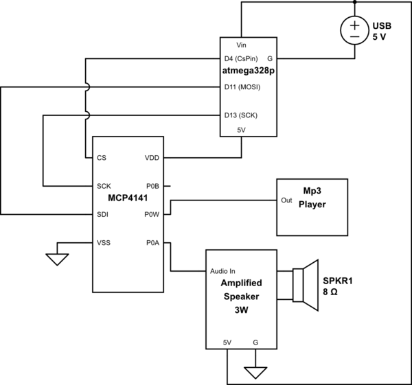
schematic

simulate this circuit – Schematic created using CircuitLab

MCP4141 datasheet: http://ww1.microchip.com/downloads/en/DeviceDoc/22059a.pdf

\$\endgroup\$
8
  • 1
    \$\begingroup\$ Resistance value of your pot is not relevant. What is relevant is how much signal the pot lets pass when set to zero. Please show your schematics. \$\endgroup\$
    – bobflux
    Commented Mar 8, 2017 at 12:21
  • 2
    \$\begingroup\$ A potentiometer is not just a variable resistance as you imply. It's a ratio of two resistances : as you increase one to 100K you also decrease the other to practically 0 giving practically infinite attenuation. So check your circuit topology - better, post your schematic here and link to the MCP4141 datasheet. \$\endgroup\$
    – user16324
    Commented Mar 8, 2017 at 12:23
  • \$\begingroup\$ I have just added the schematics... \$\endgroup\$
    – Emerson
    Commented Mar 8, 2017 at 13:12
  • 1
    \$\begingroup\$ Something to bear in mind is that the MCP4141 part you are using does not support voltages lower than Vss (aka Ground). To work correctly you are going to need to shift your voltages to Vcc/2. Typically this means AC coupling the inputs with a DC blocking capacitor and then biasing to half the supply voltage with a voltage divider made with two identical resistors. In addition DC blocking capacitors will be required on the outputs. \$\endgroup\$ Commented Mar 8, 2017 at 16:00
  • \$\begingroup\$ @PeterCamilleri .. Ok! Thanks for this information. \$\endgroup\$
    – Emerson
    Commented Mar 8, 2017 at 16:48

4 Answers 4

3
\$\begingroup\$

How can I make a digital audio panning controlled by a microcontroller?

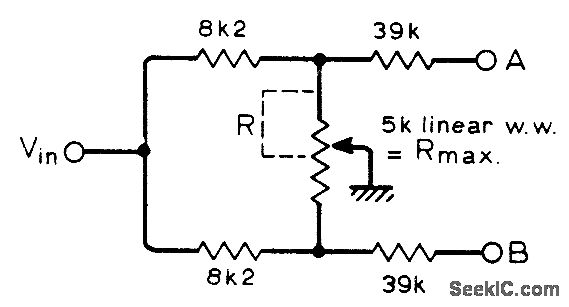
Try using this circuit: -

enter image description here

But scale up the resistors to suit your pot. The down side of using a digital pot is the wiper resistance. For the MCP4141 (100K) you used, it has a wiper resistance of up to 300 ohms, so there will be a small amount of leak through on the "muted" channel. I estimate it will be about 0.3/164 kohm if the 8k2 is scaled up to 162 kohm. In log terms that's about -55 dB. Is this enough? Only you can say.

\$\endgroup\$
15
  • \$\begingroup\$ Thank you for your answer, but the schematics is not completely clear to me....I'm not sure how to connect the MCP4141 with the 8K2 resistors.. \$\endgroup\$
    – Emerson
    Commented Mar 8, 2017 at 13:19
  • \$\begingroup\$ The MCP4141 has three pot connections - they replace the three connections and the pot above. A and B are outputs to your two power amps that feed the two speakers you mention in your question. \$\endgroup\$
    – Andy aka
    Commented Mar 8, 2017 at 15:22
  • \$\begingroup\$ I see... So in this case the pot is used to balance the signal between the 2 speakers..but this will generate a linear balance, isn't it? What I was looking for was actually a way of controlling 2 dig pots, so I could adjust the panning law by programming the microcontroller. For instance, pot #1 would go up on speaker 1, while pot 2 go down on speaker 2...then I could adjust the function when it goes up and down. I will try your method later anyway, thanks. \$\endgroup\$
    – Emerson
    Commented Mar 8, 2017 at 15:33
  • \$\begingroup\$ No, it's not a balance control. It's a panning control. You asked for a panning control. Panning is where you take one signal and move it left or right. If you want a stereo balance then this is not what you asked in your question. \$\endgroup\$
    – Andy aka
    Commented Mar 8, 2017 at 15:51
  • \$\begingroup\$ Yes, I understand panning perfectly, I've done it many times through Pure Data and other software... My purpose is panning. Sorry if I wasn't very clear. I was thinking I needed two pots for this, but it seems I was wrong. If I use just one as you suggested, I may be able to change the function and make it non-linear as well... I just realised that. \$\endgroup\$
    – Emerson
    Commented Mar 8, 2017 at 16:46
2
\$\begingroup\$

Since you say the audio is already in digital form, do the gain adjustments digitally. For each incoming sample, multiply it by (1-PAN) to the first speaker and PAN to the second. PAN is a variable that goes from 0 to 1 to control how much the sound is panned from the first speaker to the second.

Added

I was trying to show the conceptually simple way to do this. However, as Colin_s pointed out in a comment, linearly blending the voltage won't give you perceived constant amplitude during the pan. You need to keep the sum of the squares of the voltages constant, not the sum of the voltages as in the example above.

Again though, you already have a digital processor, so this is very easy to do. You can either compute the correct fraction into each speaker on the fly, or use a pre-computed lookup table.

Note that doing a constant-power pan is something the analog solutions don't do well, at least not easily. This is better and more easily done digitally.

\$\endgroup\$
10
  • \$\begingroup\$ Hi, thank you. I know how to do it digitally, I've done many times using Pure Data and a Raspberry PI.. The problem is how to use this with a microcontroller. I appreciate your answer anyway. \$\endgroup\$
    – Emerson
    Commented Mar 8, 2017 at 12:42
  • \$\begingroup\$ You could use a better microcontroller, the parts used for arduinos are painfully slow in comparison to any half decent modern part. \$\endgroup\$
    – Andrew
    Commented Mar 8, 2017 at 12:45
  • \$\begingroup\$ @Olin The problem with using that method for panning is that in the with the signal in the centre you get half the power as you do when panned hard left or right. (p = i^2 * R, ignore R assuming it's constant) Panned hard left left = sample, right = 0, power = left^2 + right^2 = sample ^ 2 whereas centre panned left = 0.5 * sample, right = 0.5 * sample, power = 0.25 * sample ^2 + 0.25 * sample^2 = 0.5*sample^2. The solution is to use left = sample*sqrt(1.0-panning); right= sample*sqrt(panning); \$\endgroup\$
    – Colin
    Commented Mar 8, 2017 at 12:54
  • \$\begingroup\$ Yes, I know this... I will get a linear panning. The square root is only one possibility between other panning laws. But before adding the maths to the program, I need to start linearly. Thanks. \$\endgroup\$
    – Emerson
    Commented Mar 8, 2017 at 13:13
  • \$\begingroup\$ Andrew, what other microcontroller do you suggest then? \$\endgroup\$
    – Emerson
    Commented Mar 8, 2017 at 13:22
1
\$\begingroup\$

As an alternative to the digital potentiometer, consider using an analog VCA (voltage controlled amplifier). You can drive the voltage control input with an analog output from your micro.

You can find integrated VCAs designed for the audio industry which have an inherently log control law - this will address difficulties and limitations associated with linear R-DACs. Check out THAT corporation.

This approach will have some associated analog design challenges, but will offload the amount of work to do in the digital domain!

\$\endgroup\$
1
  • \$\begingroup\$ I will try this as well. I've never used a VCA. It's good to know there's an alternative! Thanks! \$\endgroup\$
    – Emerson
    Commented Mar 8, 2017 at 19:21
1
\$\begingroup\$

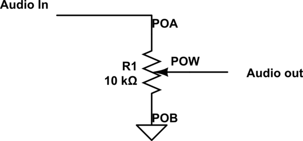
It appears from your drawing that you are using the potentiometer as a simple series resistor. For a full-range volume control, you need to use the pot as a voltage divider, like so:

schematic

simulate this circuit – Schematic created using CircuitLab

\$\endgroup\$
1
  • \$\begingroup\$ This has worked, although it added a lot of noise, which I think it's because of the VSS. As @PeterCamilleri commented on my question: "to work correctly you are going to need to shift your voltages to Vcc/2." This is a little bit inconvenient as I don't know exactly how to do it and my electronics knowledge is very short.. So maybe I will try with another digital pot that doesn't require this, as now I know the resistance is not so important. Thanks. \$\endgroup\$
    – Emerson
    Commented Mar 9, 2017 at 16:21

Your Answer

By clicking “Post Your Answer”, you agree to our terms of service and acknowledge you have read our privacy policy.

Not the answer you're looking for? Browse other questions tagged or ask your own question.