0
\$\begingroup\$

I've built a charger for my 7.2v 3000mAh battery using MAX712 IC.
Here is the datasheet:
http://pdfserv.maximintegrated.com/en/ds/1666.pdf

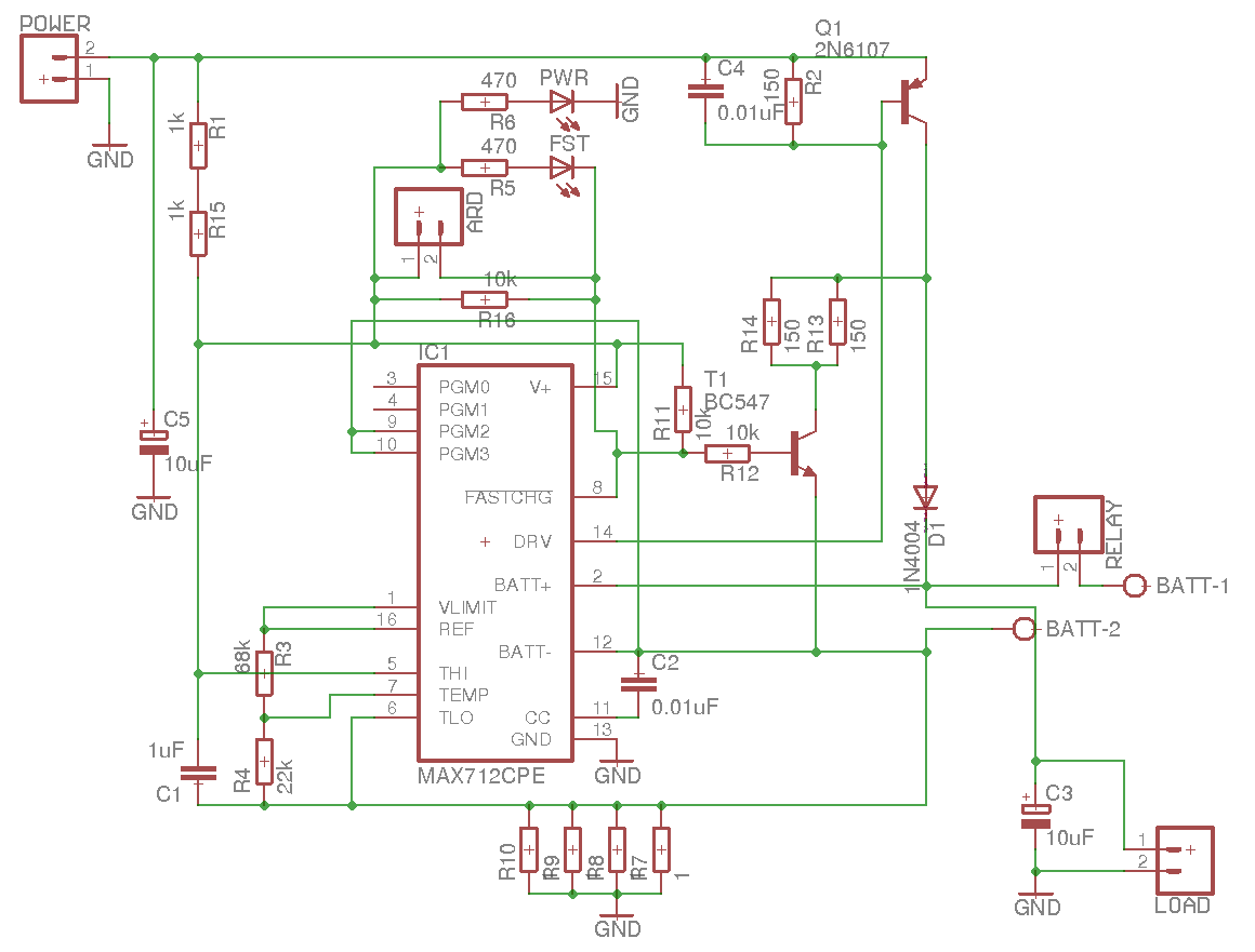
This is the schematic of my charger:
enter image description here

It's almost a schematic from datasheet.
Calculations were done with the help of this excellent article: https://www.rcgroups.com/forums/showthread.php?527385-Building-the-Perfect-Nickel-Chemistry-Charger-Part-II

Here are my values:

  • Power source: 15V 3A
  • Rsense: 0.25Ohm - 4 1Ohm in parallel.

The IC tries to maintain 0.25V across Rsense(R7,R8,R9,R10 in my schematic), so 0.25R gives (0.25V/0.25R = 1A) of fast charge current.

When I plug the battery in and turn the thing on I get 1A flowing to the battery.

The problem I'm getting is that diode D1 (1N5404 rated 3A - schematic says 1N4004, but I've replaced it on the board) and 2N6107 are getting very hot (can't hold a finger on it for more than a few seconds) on both of them (Q1 even has a heatsink).

According to this formula Q1 should dissipate 9W:

(Q1 pwr dissipation) = [ (DC IN) - (min. battery voltage) ] * (max. charge current) = (15 - 6) * 1 = 9W

The article never mentioned that D1 should be very hot, not any other article I've found, which makes me think something is wrong even though battery gets the correct 1A current.

Any ideas why they might be getting too hot? Any other info I can provide?

\$\endgroup\$
5
  • \$\begingroup\$ Your schematic says D1 is a 1N4004. Is like to confirm the 5404 from your text is correct! \$\endgroup\$ Commented May 14, 2017 at 8:13
  • \$\begingroup\$ 9W is a lot of power. What is the thermal resistance of your heatsink system? \$\endgroup\$ Commented May 14, 2017 at 8:15
  • \$\begingroup\$ I had 1N4004 originally, but then replaced it with 5404 hoping it would help with the heat. The heatsink I'm using is this one: aliexpress.com/item/… \$\endgroup\$
    – Leonti
    Commented May 14, 2017 at 8:25
  • \$\begingroup\$ I can use a bigger heatsink for the transistor - I also have 5K/W heatsink. If I understand correctly it would give 5K*9K = 45 degrees over ambient temperature, so the temperature should be 75C. Current heatsink is smaller, so I'm not surprised that it's so hot now. What about the diode? Should it be so hot? \$\endgroup\$
    – Leonti
    Commented May 14, 2017 at 8:39
  • \$\begingroup\$ To be completely honest, if you're charging a 7.2 V battery from a 15 V input, you should probably just use a switchmode IC instead of this linear one. Maxim has such, and you should feel encouraged to consider sampling those! The circuit above isn't really "simple", so you won't get a lot of additional complexity by just abandoning the MAX712 and going for e.g. a DS2715 \$\endgroup\$ Commented May 14, 2017 at 11:44

2 Answers 2

7
\$\begingroup\$

For starters: Electronics can get hot. Very hot, in fact. The diode you are using is rated to 150 degrees Celsius. I would advise you to really avoid getting anywhere near that but what I'm trying to get at is that "I can't touch it with my finger so it must be too hot" is a very bad metric - I would be surprised if you can hold your finger on something that is above 45-50 degrees C for anymore than a few seconds. Hence, it could be that the part is 60-70 degrees (which is just fine).

Let's run some numbers - keep in mind that I'm using a lot of "rouded" values since this is just a back-of-the-envelope calculation which I wouldn't expect to be accurate within more than 20% anyways:

The Diode

The diode's datasheet shows that we should expect about 1 volt drop at 1A of current. It also gives us about \$R_{\theta ja} = 20\ K/W\$ (but this is assuming a large lead length. I don't know if you have the part flush on the board or not. Let's assume not - if you do, the thermal performance will be even worse). Given about 1W of dissipation, you need another 20C above the ambient. That's already going to be about 40 degrees, and it's a best-case scenario. If you don't have the 9.5mm lead length mentioned in the datasheet, it's going to get a good amount hotter (I could easily imagine the \$R_{\theta ja}\$ being twice or even three times as large if it's mounted flush to the board with no large copper pads).

There is also the question of where you got the part - since you mentioned a heatsink from aliexpress, did you also get your parts from aliexpress? If so, there is always a good chance that the diode you recieved is a fake, and is in fact a far less capable diode.

The Transistor

9W is a lot of power, and I very much doubt that that little heatsink you posted in the comments will be able to dissipate that reliably. You already have about \$R_{\theta jc}=3\ K/W\$, so you are looking at a junction temperature of at least 20 degrees above ambient. Even with the heatsink you suggested (5K/W) you are going to get another 45 degrees on top of that, so 65 degrees in total - at a room temperature of 20 degrees Celcius, that's a junction temperature 85 degrees Celcius, and your heatsink sitting at about 65 degrees Celcius!

In other words, it seems reasonable that both get quite hot.

\$\endgroup\$
6
  • 1
    \$\begingroup\$ Have an upvote for actually doing some math (unlike my answer) :) \$\endgroup\$
    – metacollin
    Commented May 14, 2017 at 9:08
  • \$\begingroup\$ Thanks, now I understand. Calculating heat dissipation is something new to me, so I didn't know what to expect, so when things get too hot I automatically assumed that I made a mistake in my circuit. Glad to know that's not the case. So what are my options? Should I just get a bigger heatsink and replace diode with the Schottky diode as @metacollin suggested? \$\endgroup\$
    – Leonti
    Commented May 14, 2017 at 9:16
  • \$\begingroup\$ Depending on how the circuit works, and what you are expecting in terms of input and output and current range, you can sometimes put a series resistor in front of the transistor to take some of the load on it. (You will still disipate the same amount, but it will be spread out over more components). A bigger transistor and bigger heatsink is also possible, or two transistors (With two heatsinks - otherwise you are not gaining anything significant) with some emitter degeneration could also work. \$\endgroup\$
    – Joren Vaes
    Commented May 14, 2017 at 9:19
  • \$\begingroup\$ Also where is 3k/W comes from in "The Transistor" section? I understand 45 degrees (5*9) + 20 degrees ambient, where another 20 come from? By the way, awesome answer, many thanks :) \$\endgroup\$
    – Leonti
    Commented May 14, 2017 at 9:19
  • \$\begingroup\$ @JorenVaes Max current will always be 1A, max voltage drop is 9V What values the resistors should be? \$\endgroup\$
    – Leonti
    Commented May 14, 2017 at 9:21
5
\$\begingroup\$

No, it's not getting 'too hot'. No where in the field of electronics is 'too hot' defined as 'too hot to touch.'

Electronics get hot. This is a fact of life. Data sheets generally don't tell you if a certain component will get hot because you're supposed to know what things will get hot, how hot they'll get, and why. Power electronics is as much thermals as it is electronics.

And there is definitely no unwritten assumption that parts will always be cool enough to touch without burning you. In fact, this is rarely the case. That 1N5404 diode? It's maximum operating temperature is 150° C. If it isn't exceeding that temperature, then it isn't getting 'too hot'. There is nothing wrong with it operating continuously at 140°C for a long time, and in many real devices, diodes can and will operate that hot. Usually only when the ambient temperature as at the highest the product is rated, but still, it happens.

If you open up any old electronics with a bridge rectifier, often you'll see discoloration of the PCB in the area around these diodes. This is because those suckers get hot. And its ok. They're designed to operate in those conditions.

There are many MOSFETs that are rated to 175°C. The new Silicon Carbide based semiconductors have a theoretical operating range of 400°C (!!), though most are limited to 200-225°C due to their packaging epoxy not able to withstand any higher.

Anyway, yes, diodes get hot. Especially when you ask one with a 1.2V voltage drop to carry 1A, like in your case. Frankly, the 1N5404 is a wildly inappropriate diode for this application. So is the 1N4004, I am not sure what Maxim was thinking. But in your case, that diode is dissipating 1.2W at least. If it is getting hot, good. That means the circuit is working. If you don't want it to get hotter than you can touch, too bad, it's going to get too hot for you to touch.

Now, if you chose a diode with a lower voltage drop, pretty much any Schottky diode, it will get a little less hot. These diodes typically have about half the voltage drop of a silicon diode, so let's call it 600mV. This will cut the heat produced in half, to 600mW. It's still going to heat up though, but not quiet as much.

To put things into perspective, imagine the size of a 1/4W through hole resistor. Try putting 1/4th of a watt through it. It will get hot enough to burn you, but it will also tolerate this temperature perfectly fine, certainly much better than your finger will. That diode is shedding 5 times that. 1.2W might not sound like much, but tiny things get hot without many joules getting added to them.

As for the transistor, of course it gets hot, even with a heatsink. That's the entire point of heatsinks. To get hot. They work better if they're hot. They convect more heat via passive airflow, and if they're black, they'll radiate some heat too. Heat is even in the name. The transistor and heatsink are always going to be hot. All that matters is that they don't get too hot. You can lower the temperature it and the heatsink will eventually reach by either

  1. Reducing the amount of power it must shed. So, make it waste less than 9W as heat. I don't think you can though with this circuit, as it's linear, and linear regulation works by burning off the excess voltage as heat.

  2. Put a larger heatsink on it (this will still warm up, but it will not reach quite as high of an equilibrium temperature).

  3. Make the room/ambient temperature cooler.

To put it bluntly, there is nothing that is wrong with your circuit, so much as something wrong with your expectations. Sorry. Heaters gonna heat.
\$\endgroup\$
3
  • \$\begingroup\$ the 1n4004 in the datasheet could just be a case of an IC designer having to build an application circuit and not being experienced with what to expect from discrete parts. In ICs, you overrate far less than in discretes because area=cost. That said, still is a very silly choice, a schottky is clearly a better suited part. \$\endgroup\$
    – Joren Vaes
    Commented May 14, 2017 at 9:10
  • \$\begingroup\$ @metacollin - thanks for the answer, it's great! I'm going to replace the diode with the Schottky one. \$\endgroup\$
    – Leonti
    Commented May 14, 2017 at 9:25
  • \$\begingroup\$ +1 for the closing sentence...other info wasn't bad, either. \$\endgroup\$
    – tjbtech
    Commented May 14, 2017 at 15:47

Your Answer

By clicking “Post Your Answer”, you agree to our terms of service and acknowledge you have read our privacy policy.

Not the answer you're looking for? Browse other questions tagged or ask your own question.