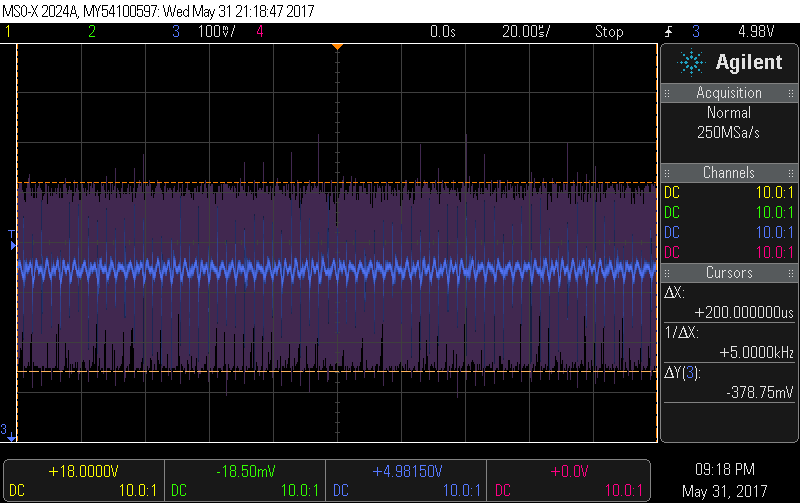
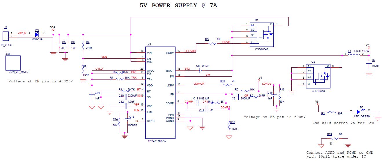
Noise seems high although as some have suggested if it works, why fix it? The Pi will have it's own bypassing capacitors that mitigate this noise. You're clearly using a commercial /professional switch chip rather than some Frankenstein 555 timer creation. The chip's data sheet has layout recommendations towards it's end. These are pretty important due to the large switch currents flowing around (and beneath) the chip. Do these recommendations match yours?
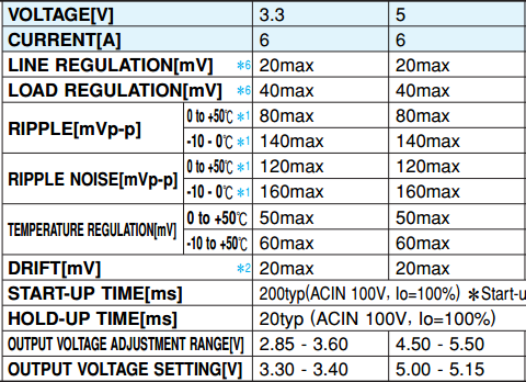
I'm assuming that your circuit is lifted straight from the data sheet. So you might expect the same ripple /noise that it gives. I can't read the screen sufficiently on my device to ascertain the noise, but is it ~30mV @ 20 MHz? I'm not sure I believe this as data sheets can offer representative information. The data sheet extract below is from this commercial PSU outputting 5V @ 6A. Ripple is 120mVp-p, higher than your chip's datasheet, but still significantly lower than your results.

If you can't reduce the noise to an acceptable level though layout improvements, you might consider anther stage of LC filtering. You'd only need uH stuff as you'd be looking to smooth frequencies in the order of 100kHz - MHz.
I can't see from your 'scope grab, but do you have 20 MHz bandwidth limiting on? You need to have that set to usefully compare noise readings between PSUs.
I also suggest you watch Dave's video regarding correct oscilloscope probe technique for measuring PSU noise. You really should do it differentially as in the video. It is likely that you'll see improved results with a better probing technique as you should be able to compensate out at lot of extraneous noise.
Personal statement: I never build switch mode power supplies unless I'm specifically trying to learn how. If I ever need a switcher, I always buy off the shelf. There's a lot of analogue /EMI /ground loop theory to absorb and digest to minimise the noise they're notorious for. Once you factor in the components, especially those weird specialist high frequency transformers and a commercially manufactured PCB, the cost differential is small. Plus you can consider any extra cost as an insurance premium for ruling out odd behaviour from an uncertain DIY switcher. Just sayin'.


