0
\$\begingroup\$

I want to construct an autonomous RF PCB module powered by a solar panel. To achieve this, I have obtained solar harvester and battery charger integrated circuits (ICs) designed to charge a Li-Po battery with a voltage of 4.1 V. Following this, my intention is to establish a connection between the power section and the RF/microcontroller (MCU) section.

To mitigate potential noise issues, it has been suggested to use a low dropout regulator (LDO.) The drawback of LDO lies in its lower efficiency compared to switching mode regulators, particularly concerning thermal power losses. This becomes especially critical in the context of solar autonomous power, where efficiency is a key consideration.

Upon my understanding, the primary source of noise is the electromagnetic interference (EMI/EMF) generated by the high frequency of the switching mode regulator. To address this, I am contemplating splitting the entire project into two distinct parts. The first part would encompass the power components, including the harvester charger, battery, and a switching mode regulator providing a 3.3 V output. The second part would involve the RF/MCU components. Power would then be transmitted from the power PCB to the RF section using wires with a length of 10-30cm. This approach is aimed at creating sufficient distance between the switching mode and the RF components to prevent EMI.

I seek your advice on whether this approach would effectively solve the noise problem, or if using an LDO remains the optimal solution.

\$\endgroup\$

1 Answer 1

2
\$\begingroup\$

That sounds like a broad question but I'll try my best to give some general info whilst keeping the answer not too long.

  • The presence of a switching regulator is enough to get both conducted and radiated EMI problems. But LDO helps to solve a limited portion i.e. radiated EMI will still be there (partly or fully).

  • If you are size-limited you may want to consider buck regulators running at a switching frequency of at least 1 MHz. In this case the harmonic content (switching noise) may contain higher frequencies with higher amplitudes. So if you run 30-centimetre long cables directly from the output of a switching regulator, depending on the switching frequency and frequency (noise) content of the output, these cables may radiate ~1/2/4 GHz (full/half/quarter wave). Good layout and filtering are required.

  • The regulator's choke can be a good source of radiated EMI. Consider shielded chokes along with good layout and, if necessary, external shielding and filtering.

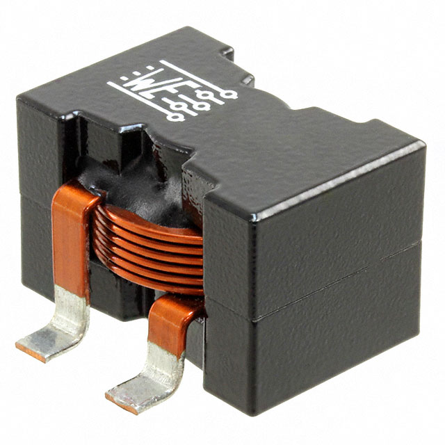
  • Flat-wire chokes have one of their legs connected to a longer wire segment due to their construction (see below). This longer wire can radiate. So, if you use such a choke don't connect this long-wire leg to the switching node.

enter image description here

  • A switching regulator tends to pollute the input line. So the supply cables can radiate. A good input filtering is required.
\$\endgroup\$

Your Answer

By clicking “Post Your Answer”, you agree to our terms of service and acknowledge you have read our privacy policy.

Not the answer you're looking for? Browse other questions tagged or ask your own question.