0
\$\begingroup\$

I wish to model a battery for a small computer game, a battery which will be subjected to heavy loads and deep discharge. The model doesn't have to be high-fidelity, just a rough approximation will do. I want to display both the current and voltage, and watch how they change as the battery runs out of juice.

I have a loose grasp of the basics, V=IR and so on, and can calculate these for a steady state circuit with an ideal power source but am lost when dealing with a more realistic battery model.

If I understand right, I can add add load to my battery, and figure out the current being drawn, and deduct that from the battery capacity in Ah, giving me a decreasing value for the "juice" left in the battery. But I get a bit lost thinking about what happens when the load is such that the current being supplied is very high. I assume the voltage should sag, but how can i model this? And is this current limit and voltage sag also connected to the available capacity of the battery?

I have read about representing a battery as a voltage source and a series resistor, but am a bit lost in how to use this. Should I be increasing the series resistance in relation to the decreasing capacity? What is the nature of that relationship, if so?

My apologies if this is not very clear, I have tried my best with the terminology.

\$\endgroup\$
8
  • 2
    \$\begingroup\$ You might start by finding a real data sheet for a cell type of interest - that will often show discharge curves at different loads. You could turn these into a "per charge removed" model and try to fit some equations, ideally getting something where you can change discharge rate over time. \$\endgroup\$ Commented Jun 9, 2017 at 19:22
  • \$\begingroup\$ Thanks @Chris Stratton, I've already looked at some data sheets, but I do not understand the maths relationship between the discharge rate curves, and how they are connected to the maximum current supply of the battery. It might also be that the answer is right on front of me, but I don't understand enough to recognize it yet. I was kind of hoping there's a connection between removing amp hours from the battery, and increasing its internal resistance, as that'd limit the voltage and current i can take out, until it falls off entirely... \$\endgroup\$
    – Innovine
    Commented Jun 9, 2017 at 19:25
  • \$\begingroup\$ Maximum current supply is an elusive metric - unless it has a shutdown circuit or ruptures/explodes, the voltage is just going to sag and the losses vs. useful power delivered shoot up. Taking a step back, do you want to model the mechanism or do you want a model that gives you an idea of how a black box will behave under conditions that interest you? \$\endgroup\$ Commented Jun 9, 2017 at 19:28
  • \$\begingroup\$ I am ok with a black box model. What I ideally want, is just to have a battery, which I connect devices to, including a voltmeter and ammeter. Then the readings on these meters would decrease, until the battery is depleted. Power management is important to my game, so turning on and off devices, and the effect on the battery (ie some devices browning out or malfunctioning when too many are turned on) is highly desired. Eventually I might even add temperature effects, requiring heating/cooling the battery, and its own internal heat generation, but thats a different question :P \$\endgroup\$
    – Innovine
    Commented Jun 9, 2017 at 19:31
  • \$\begingroup\$ Let the series resistance be constant, unless you also want to model wear and tear. The resistance will become more significant as voltage drops. \$\endgroup\$
    – Dampmaskin
    Commented Jun 9, 2017 at 19:33

3 Answers 3

1
\$\begingroup\$

You could model the power consuming "things" as constant resistance loads, all in parallel. A high resistance is a light load, and vice versa.

To find the total resistance of all parallel loads, use this equation:

R = 1/((1/R1) + (1/R2) + (1/R3) ...etc...)

If you have multiple batteries in parallel, you find the total resistance of all batteries using the same equation for the battery resistances.

The load resistance(s) is in series with the battery resistance(s), so next step is to simply add these two totals together. Rbatt + Rload.

Then use the equation Power = Voltage*Voltage/Resistance to determine the performance of each load. The resistance here is the resistance of the individual load. Power equals performance.

As the battery voltage drops, you will see that the performance of each load will drop drastically. Also, when you have many loads connected, the battery resistance will be significant (it will cause the voltage to sag). With few loads, the battery resistance will have less of an impact.

If you want to model a Lithium battery, start out at 4.2 V when full. When the battery reaches 3 V; it's "flat", and the power should be cut. If you want to model a NiMH battery, start at 1.5V and cut at 0.8V or so. Or you could set these values anywhere you want.

The tweakable values here are

  • full battery voltage
  • empty battery voltage
  • load resistance (can be different for each individual load)
  • battery resistance (can be different for each type of battery)
  • battery capacity (mAh, different for each type of battery)

If you want to stay somewhat realistic, you do not want to combine batteries with different max and min voltages in parallel.

However, if you implement the option to put batteries in series as well as parallel, you open up a whole new realm of possibilities: The output voltage is doubled, the battery resistance is doubled, the capacity in mAh stays the same.

To model how the battery gets depleted, you indeed need a charge state vs voltage curve. Find a real one on the Internet and build yourself a dictionary, or make an equation that approximates it, or something to that effect.
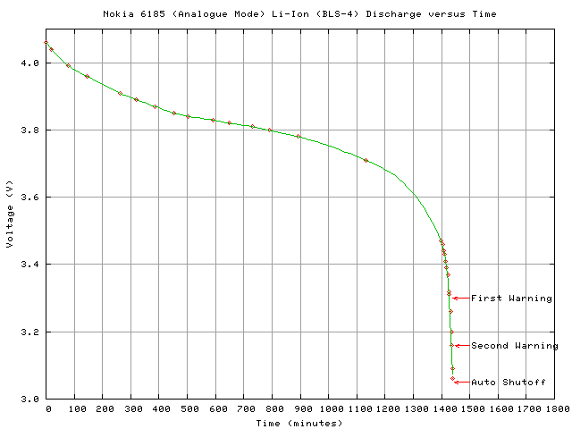
Typical discharge curve of a Lithium battery

If you want to simplify this a lot, you can just say that the battery is at max voltage (e.g. 4.2V) when it's full (has all the mAhs), and at min voltage (e.g. 3V) when it's empty (has zero mAh left). At any charge state between 0 mAh and full mAh, you can interpolate between these two voltages to find the battery voltage at that charge state. This will give you a linear discharge curve, not perfect, but it will serve as a placeholder.

Let's say that the battery capacity is 1000 mAh == 1 Ah == 60 amps-minute == 3600 amps-second. Let's also say that the load is 1 Ohm and the internal resistance of the battery is 0.1 Ohm. We start with a full battery at 4.2 V.

Then the algorithm could go like this, with one second ticks:

  • Find the current, the first tick it is 4.2V / 1.1 Ohm = 3.82A.
  • The load is producing 3.82A * 3.82A * 1 Ohm = 14.5924W, so you know the performance.
  • While 3.82A * 3.82A * 0.1 Ohm = 1.45924W is lost as heat in the battery.
  • The battery started out with 3600 amp-seconds, but now it only has 3600 - 3.82 = 3596.18 amp-seconds left.
  • Now use your discharge curve to find the new battery voltage, let's say it's already dropped to 4.15V.
  • Rinse and repeat.

You can now model the charge state, the battery voltage, and the appliance performance second by second.

\$\endgroup\$
6
  • \$\begingroup\$ This is very helpful, thanks! Eventually I would like the option to add multiple batteries, in both parallel and series configurations, but I'll need to understand the single battery case first. When you say "as the battery voltage drops" I am a bit lost... what causes this drop? I can see that to maintain V=IR as I exceeds some arbitrary max I value the voltage needs to go down, is this what you are referring to? \$\endgroup\$
    – Innovine
    Commented Jun 9, 2017 at 20:54
  • \$\begingroup\$ No battery chemistry keeps an absolutely constant voltage during the discharge. Lithium batteries come pretty close, but it's still not flat. If you want a very simple model, you can say that the battery is 4.2V when full and 3V when flat, and interpolate anything in between, but in reality the curve is more S shaped. Here: lenrek.net/experiments/nokia/discharge.2002-11-09.png \$\endgroup\$
    – Dampmaskin
    Commented Jun 9, 2017 at 21:00
  • \$\begingroup\$ Excellent, thanks. The description of the algorithm was a massive help, thank you! I'll give some other guys a chance to answer too before accepting, but this has basically answered everything I wanted. Much appreciated! \$\endgroup\$
    – Innovine
    Commented Jun 9, 2017 at 21:16
  • \$\begingroup\$ Sorry, one more question :) How does the C rating fit into this example? For instance if it was a 10C battery, the max safe load would be 0.42 ohms... what would happen if i added more load, which brought that to 0.3ohms? \$\endgroup\$
    – Innovine
    Commented Jun 9, 2017 at 21:26
  • \$\begingroup\$ The C rating is set by the manufacturer. It's a roundabout way of stating the max safe continuous amp draw, and has no direct relation to load resistance. The C rating = max safe discharge current (A) divided by battery capacity (Ah). If the user doesn't respect this limit, the waste power (current squared * internal battery resistance) might heat up the battery to over ~130 deg C, at which point a nasty and self sustaining exothermic chemical reaction will be set off. It's called thermal runaway, the consumer grade version of a nuclear meltdown. 8) \$\endgroup\$
    – Dampmaskin
    Commented Jun 9, 2017 at 21:37
0
\$\begingroup\$

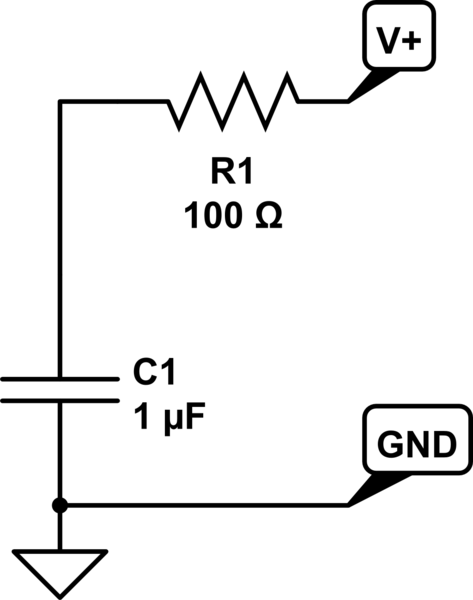
I believe what you are looking to model is something like the following. It is an extremely crude representation, and the values I have should be ignored(for game balance purposes these can be tweaked), however it will reduce the voltage as current increases and/or the battery discharges. The initial voltage across the cap can be whatever value you need for the fully charged battery(again for game balance).

schematic

simulate this circuit – Schematic created using CircuitLab

\$\endgroup\$
0
\$\begingroup\$

You haven't said what sort of battery. To a rough approximation, a standard dry cell battery (zinc carbon or alkaline) is a constant voltage source in series with a resistor. The resistance rises as the battery discharges.

In reality, the voltage drops, but not by a great deal until the battery is totally flat. Also, with a real battery, if the large load is removed, the resistance will drop a bit as the battery recovers over a few hours.

Other battery types could be modelled similarly, but tweaking the parameters. A lithium ion battery has a much lower internal resistance, but the voltage drops significantly (from about 3.7V down to 3.0V) as it runs down.

\$\endgroup\$
1
  • \$\begingroup\$ I don't have to stick to modeling existing batteries. I can set all the properties and parameters at will. The battery is used in game for powering a small one-man space capsule, so something like 24-48v and 400Ah, and likely more than one battery. I can adjust the parameters to give interesting gameplay (and even offer a selection of batteries.. ie this one is best for a constant, low current draw, etc...) What I am doing right now is just understanding what these parameters actually are, and how batteries behave in general when severely loaded and/or depleted. \$\endgroup\$
    – Innovine
    Commented Jun 10, 2017 at 6:49

Your Answer

By clicking “Post Your Answer”, you agree to our terms of service and acknowledge you have read our privacy policy.

Not the answer you're looking for? Browse other questions tagged or ask your own question.