2
\$\begingroup\$

I am doing a classic LED - sound reactive project. The only thing that is bothering me is that my electret microphone (MAX4466 from Adafruit) is clipping, and it is because the maximum gain of this microphone is 125dB. Usually it is enough, but for not for my project.

I need to put the microphone inside of a drum (kick drum.) The signal clips every time I hit hard on the drum. I need to find a way to reduce the microphone's sensitivity even more. I thought about the following solutions:

  • Put something in front of the microphone to attenuate the sound.
  • Unsolder the electret microphone, and put another one that has a higher SPL.
  • Maybe change the resistance of the adjustable gain to increase the maximum gain (instead of the 10k to 100k ohm, I solder a higher resistance.)

I know that the difference between the maximum and minimum gain will stay the same. With a microphone that detects sound from 25dB to 125dB, lets say I attenuate sound, it might detect 45dB to 145dB. In my case, I don't care about the lower sounds, I am only looking for the loud BOOMs.

I looked everywhere on the internet, but everyone wants a better sensitivity, and I am looking for the opposite.

\$\endgroup\$
6
  • \$\begingroup\$ The MAX4466 from Adafruit has adjustable gain, have you tried to adjust — i.e. lower — it actually? \$\endgroup\$
    – user59864
    Commented Jun 11, 2017 at 19:30
  • \$\begingroup\$ Yes it is set to the lowest sensitivity, and it is still not enough \$\endgroup\$
    – Lalous
    Commented Jun 11, 2017 at 19:44
  • \$\begingroup\$ You need to find out if it is the amplifier or the microphone itself that is hitting its limits. Electret microphones are usually rated for a maximum sound pressure level. Your drums could easily exceed the rating of the microphone. You would use an oscilloscope connected to the microphone itself to see if its output is distorted. \$\endgroup\$
    – JRE
    Commented Jun 11, 2017 at 19:45
  • \$\begingroup\$ If you don't mind modest fidelity then I've made carbon granule microphones using battery carbon (back in the day.) It might actually be insensitive enough for you. Today, you'd probably use activated filter carbon from an aquarium store. This link, books.google.com/…, shows you almost how I did it (though I used metal washers.) But this video shows another way: youtu.be/uAnlmoei_Co \$\endgroup\$
    – jonk
    Commented Jun 11, 2017 at 19:47
  • 1
    \$\begingroup\$ @Muze: Correcting errors in a question is fine. Changing correct things ("electret microphone") to nonsensical things ("electric microphone") is not OK. Try to be certain of your own words before correcting some one else's words. \$\endgroup\$
    – JRE
    Commented Apr 4, 2019 at 7:39

3 Answers 3

2
\$\begingroup\$

The "Linkwitz mod" reduces the sensitivity of an electret mic and allows the mic to have very loud sounds (from a drum) with low distortion. You cut the pcb trace that connects the metal case to the source pin of the Jfet allowing you to solder a wire to the small piece of pcb trace for the cable shiels and as a grounded wire. Use a shielded pair of wires to connect the modified mic to the modified preamp. Then you connect the source wire of the Jfet as the output and it needs a resistor to ground. Connect the drain pin of the Jfet to a supply voltage. Here is a video of the mod:
https://youtu.be/dSPQf42JgbI

\$\endgroup\$
2
\$\begingroup\$

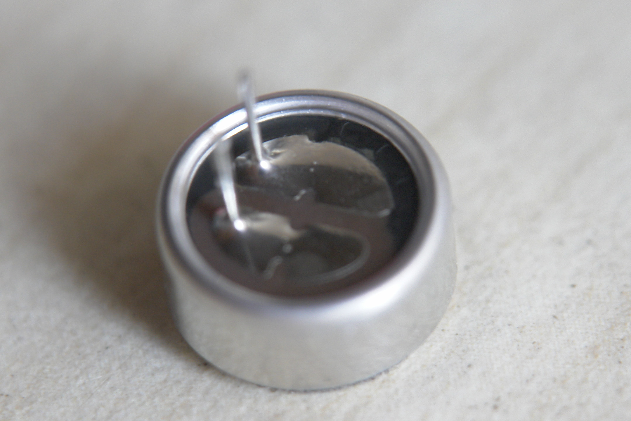
When you unsolder the microphone, you'll find the layout on the bottom somewhat like the following (here a Panasonic WM-52B): enter image description here There are two solder pads that are almost split in the middle. In this picture, the upper solder pad has 3 traces to the metal case on one part of its semi-split, and one of its pins (the FET source) on the other side.

What you do is complete this upper split with a scalpel. Then you cut the trace on the PCB from the source pin (it will lead to analog GND) and solder a resistor of maybe 10k across that cut. You then add an isolated wire to the bottom of the microphone on the case-side of your fresh cut there, and solder the mic back in, with the extra case wire going to analog GND like it did previously.

This reduces the level on the ends of the mic by two mechanisms: the larger resistance reduces the current that the FET can modulate. More importantly, the FET now partially acts as a source follower that lets the source pin voltage chase after the gate. Since clipping occurs when the gate-source voltage difference reaches the pinch-off voltage, allowing the source to chase after the gate gives you additional headroom.

Essentially, it changes the (most sensitive) 2-wire configuration into, well, a 2½-wire configuration. This leaves most of the circuit around the capsule intact and does not change the output polarity (pressure still produces negative output changes on the drain) but adds negative feedback reducing the gain.

10k is just a ballpark figure that should be good for a significant change. Much lower, and you have little effect. Much higher, and the noise across the resistor would make it more advisable to change to a true 3-wire configuration where the capsule output voltage is taken from the source of the capsule FET rather than the drain, the drain is connected to VCC with no additional resistance, and the source has a load resistor against GND.

The case still needs to stick with GND in that case.

\$\endgroup\$
0
\$\begingroup\$

I would just wrap the microphone in foam tape or get a really thick foam cover and turn up the gain. I know it is not the electrical way of doing it, but this is why they use fussy booms to take out all the background noise.

\$\endgroup\$
1
  • \$\begingroup\$ Do you mean fuzzy? \$\endgroup\$
    – Aaron
    Commented Dec 22, 2021 at 19:34

Your Answer

By clicking “Post Your Answer”, you agree to our terms of service and acknowledge you have read our privacy policy.

Not the answer you're looking for? Browse other questions tagged or ask your own question.