1
\$\begingroup\$

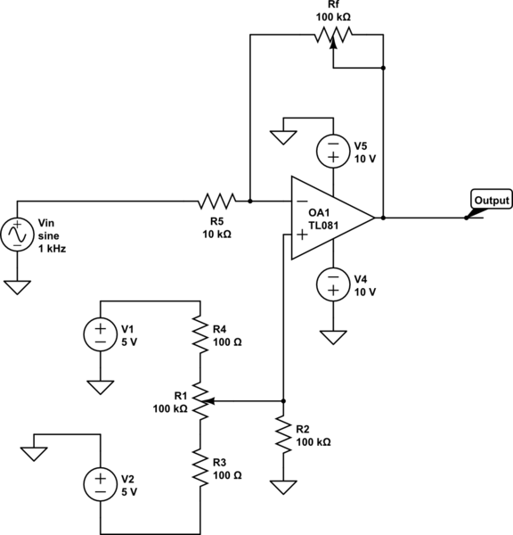
I have signal coming from DAC ranging from 0 to -1V. I want to be able to adjust the VPP from 0 to 10V and adjust the offset from 0 to +/-5V. To do this, I am using digital potentiometers (Rf for VPP and R1 for offset). Does this circuit seem viable?

schematic

simulate this circuit – Schematic created using CircuitLab

The other option I thought to use was a differential amplifier circuit as stated in :Differential amplifier opamp with gain and offset adjustment

Thank you for your help!

\$\endgroup\$
4
  • \$\begingroup\$ Offsets are usually a couple of mV or less. There is little point in making the voltage at R1 vary from -5 to +5 V where +/- 100 mV would suffice. Also why not simply ground the opamp's + input and use the offset inputs of the opamp to compensate for offset. That's what they're for. That's what almost all circuit designers do. \$\endgroup\$ Commented Jun 23, 2017 at 19:45
  • \$\begingroup\$ I'm sorry. Im a little confused. I want the output to vary by +/-5 volts upon my choosing. Is the offset input a separate pin? The opamp I picked doesn't seem to have it. Thank you for your time. \$\endgroup\$ Commented Jun 23, 2017 at 19:50
  • \$\begingroup\$ Yes, the circuit will basically work as you propose. Make sure your programmable pot on the feedback loop can handle the frequency range you need. You may be able to eliminate the separate +/- 5 volt supplies by simply changing your resistive divider scheme and power it from your +/-10 volt supply as long as your programmable pot can handle the current. \$\endgroup\$
    – Glenn W9IQ
    Commented Jun 23, 2017 at 20:11
  • \$\begingroup\$ Awesome. Thank you for your response. I appreciate the help! \$\endgroup\$ Commented Jun 23, 2017 at 20:40

1 Answer 1

1
\$\begingroup\$

Your basic idea is OK. You have a inverting amp with adjustable gain from 0 to 10. This gain can be about a adjustable DC level.

However, some of the details need work:

  1. R4 and R3 are silly. They are each 0.1% of the pot. That is less than the precision you can set the pot to. In any case, I can't even guess what you think they do for you.

  2. R2 is worse than silly since it loads the output of R1, and thereby reduces the offset range. You need the full ±5 V to get the ±5 V offset range you specified.

  3. You really should filter the offset voltage. Stuff happens, and noise can get picked up. Also, any noise on the +5 and -5 V supplies go directly to the offset voltage, which goes directly to the output signal.

    The TL081 has very high input impedance. You can easily afford to put 100 kΩ in series with the output of R1. That gives you a impedance from 100 kΩ to 125 kΩ for a cap to work against. If a human is adjusting the pot, then you can filter down to about 1 Hz. 125 kΩ and 1 Hz requires a 1.6 µF cap. A 1 to 2 µF cap should be fine. The only drawback of over-filtering is that the result of the pot adjustment will appear to lag.

  4. A TL081 can't put out 10 V with a 10 V supply. Read the datasheet. These things need quite a lot of headroom at both ends. They can take ±15 V supplies, so all you need is a larger supply range.

    Again, you really need to read the datasheet, especially for parts like opamps that have lots of parameters and so many many variations out there.
\$\endgroup\$
2
  • \$\begingroup\$ I understand what you mean. I should've paid more attention to the circuit I made. I drew it just to check if the concept behind the layout would work. Next time, I will take every detail into account. As per your third point about filtering, do you know if any links or reference material you can point me to so I can better understand how to implement filters for my designs? My knowledge about filters is fairly limited. Again, thank you for your help. I appreciate it. \$\endgroup\$ Commented Jun 23, 2017 at 20:45
  • \$\begingroup\$ Regarding your second point, would you recommend simply removing R2 entirely? \$\endgroup\$ Commented Jun 23, 2017 at 20:47

Your Answer

By clicking “Post Your Answer”, you agree to our terms of service and acknowledge you have read our privacy policy.

Not the answer you're looking for? Browse other questions tagged or ask your own question.