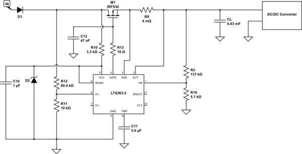
I was asked to protect a DC/DC Buck converter against overvoltage and overcurrent event. During my research, I found the LT4363-2 component from Linear Technology that is defined as a High Voltage Surge Stopper with Current Limit. After reading its datasheet, I concluded that this component would do the work, would do what I was looking for.
The DC/DC converter is a [12V - 36V] Input / 12V Output buck converter (120W).
The nominal input voltage of the system is VIN = 28VDC. My problem is that when I turn on the system at its nominal value (28V), the system doesn't work : I don't have 12V at the output of the Buck converter, the LT4363-2 seems to be under protection fault. However, everything works fine if the input voltage when I turn on the system is between 12V and 19.5V. In this case, when the system is on and can supply supply the load, I can increase the input voltage up to 28V without having the system shutting down.
Here below my schematic :

simulate this circuit – Schematic created using CircuitLab
So :
\$ D_1\$ protects against reverse polarity connection.
\$R_{11}\$ and \$R_{12}\$ create a voltage divider. Their value are chosen so that the voltage seen by the UV pin is equal to 1.275V when the input voltage is equal to 9V. Thus, when \$V_{IN} < 9V\$ the system can't supply the load (undervoltage condition).
\$D_{2}\$ will limit the \$V_{IN}\$ voltage to less than 63V.
Since the minimum required voltage at the VCC pin is 4V, \$R_{10}\$ is chosen so that when \$V_{IN} = 9V\$, \$V_{CC} = 4V\$ at least.
\$C_{10}\$ is here to filter high transients up to 250V with a pulse width less than 300us.
\$R_{2}\$ and \$R_{16}\$ create a voltage divider to adjust the output clamp voltage value. Their value are chosen so that the output voltage clamp is 35.5V.
\$R_{9}\$ is a sense current resistor. It is chosen so that when \$I_{OUT} > 12.5A\$, the voltage seen between \$SNS\$ and \$OUT\$ pins is equal to 50mV leading the a overcurrent condition.
\$C_{11}\$ is chosen so that the N-MOSFET turns off after 310ms under overvoltage condition, and after 61ms under overcurrent condition. This value also set the cool down time (when expired, the MOSFET turns back on) to 18.83s.
I have checked multiple times my calculus and I don't understand where the fault may be. Right now I do not have access to the system so can't make complementary measurements. But with what I just provide for the moment, is anyone have an idea about my issue ?
Thanks !
