1
\$\begingroup\$

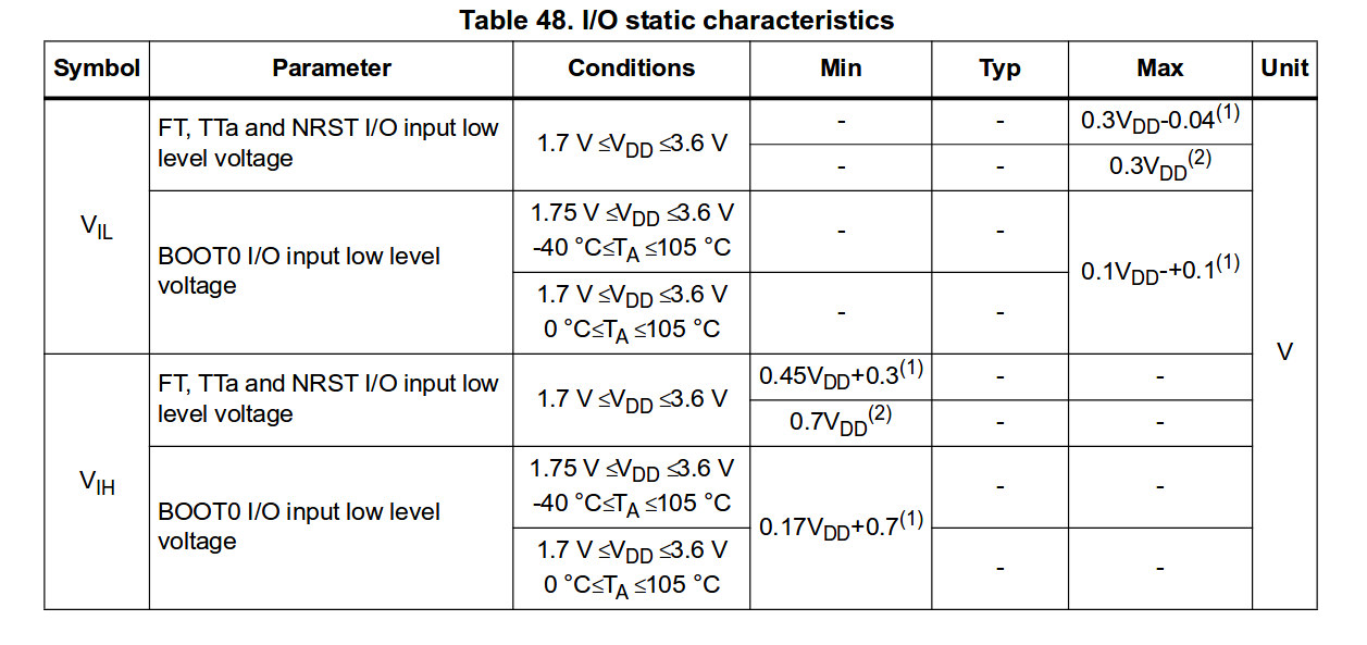
The stm32f4 discovery datasheet DS8626 specifies vil and vih as below enter image description here
So I have some questions based on the documentation

  1. How do I know that what value VDD is operating at if I use the usb to power the board?

  2. Why are there two Min or Max values for Vil and Vih? Does that have to do with CMOS vs TTL idea? Which one do I choose? .

Background

I am trying to make a simple circuit where I have a push button and led on a bread board make the led blink with the push button using the pins on the stm32f4. Basically rather than using the push button/led that is available on the board I want to try making the same circuit but just on a breadboard and use the stm32f4 board to process inputs from the push button to get some practice.

So I am confused about how much voltage I need to supply push button vs what the board needs to determine logic levels.

\$\endgroup\$

3 Answers 3

1
\$\begingroup\$

The stm32f4 discovery datasheet DS8626

That is actually the datasheet for the controller sitting in the middle of your board. The board itself is documented in UM1472.

How do I know that what value VDD is operating at if I use the usb to power the board?

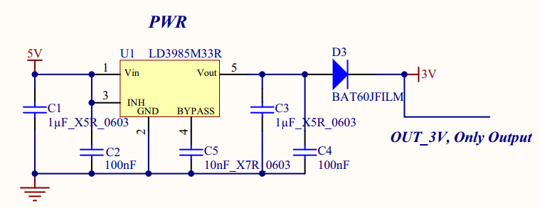
Looking at the schematics in the User Manual above, there is this circuit.

enter image description here

According to the relevant datasheets, VOUT of the LD3985M33R is 3.3V, the forward voltage drop on BAT60JFILM is 0.3 to 0.4 V at reasonable currents, that gives 2.9 to 3.0 V. But the actual voltage should not matter at all, because you are going to power the switch with the same VDD, or connecting the switch to ground, and pulling up the pin with a resistor to VDD, aren't you?

Why are there two Min or Max values for Vil and Vih?

It is explained in the footnotes right below the table.

  1. Guaranteed by design.
  2. Tested in production.

There is theory and practice, you know...

So I am confused about how much voltage I need to supply push button vs what the board needs to determine logic levels.
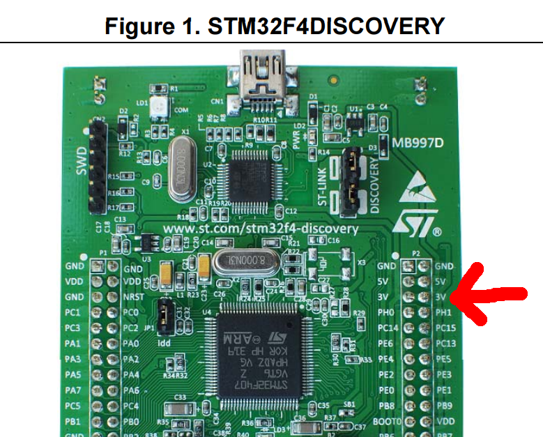
Just power your button with the 3V pin on the discovery board.

enter image description here

\$\endgroup\$
0
\$\begingroup\$

How do I know that what value VDD is operating at if I use the usb to power the board?

It does not matter as ~5V is too much for this micro so you need to lower it to max 3.6V (usually 3.3V, sometimes 2.5 or 1.8 depending on your application). So you know the Vdd as you need to design the supply circuit anyway.

Why are there two Min or Max values for Vil and Vih? Does that have to do with CMOS vs TTL idea? Which one do I choose

You do not choose anything. your peripherals (on the board need to supply proper signal voltages, otherwise your micro will not know what level it is.

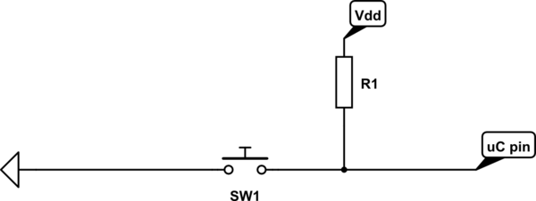
schematic

simulate this circuit – Schematic created using CircuitLab

\$\endgroup\$
0
\$\begingroup\$

According to the notes at the foot of the table, items marked with a 1 are the value by design, items with a 2 are as tested. In other words the ones with a 1 are the guaranteed minimum or maximum and those with a 2 are typical values.

You should design your board to use signals where the voltage level is not more than the (1) value or Vil for a zero and not less than the (1) value of Vih when high.

For a simple push-button that means having the button pull to ground on one side and having the other side attached to the device with a pull-up to your Vdd supply.

The device is intended to be operated from 3.3V as such you will need to regulate the USB 5V output down to that level.

\$\endgroup\$

Your Answer

By clicking “Post Your Answer”, you agree to our terms of service and acknowledge you have read our privacy policy.

Not the answer you're looking for? Browse other questions tagged or ask your own question.