5
\$\begingroup\$

I work for an escape room business, I create tricks and props using arduinos. Most of the time the Arduino has to take input from a player using buttons, sensors, etc. and locks/unlocks and electromagnetic lock for either a door or drawer or something. The locks are always controlled via relays and their respective arduino.

The problem is that installation can get quite messy and unruly since we have so many locks and arduinos that need power supplies. So for now I've been using a 12V power supply that powers the arduino through a 7805 voltage regulator as well as the lock. As shown here.
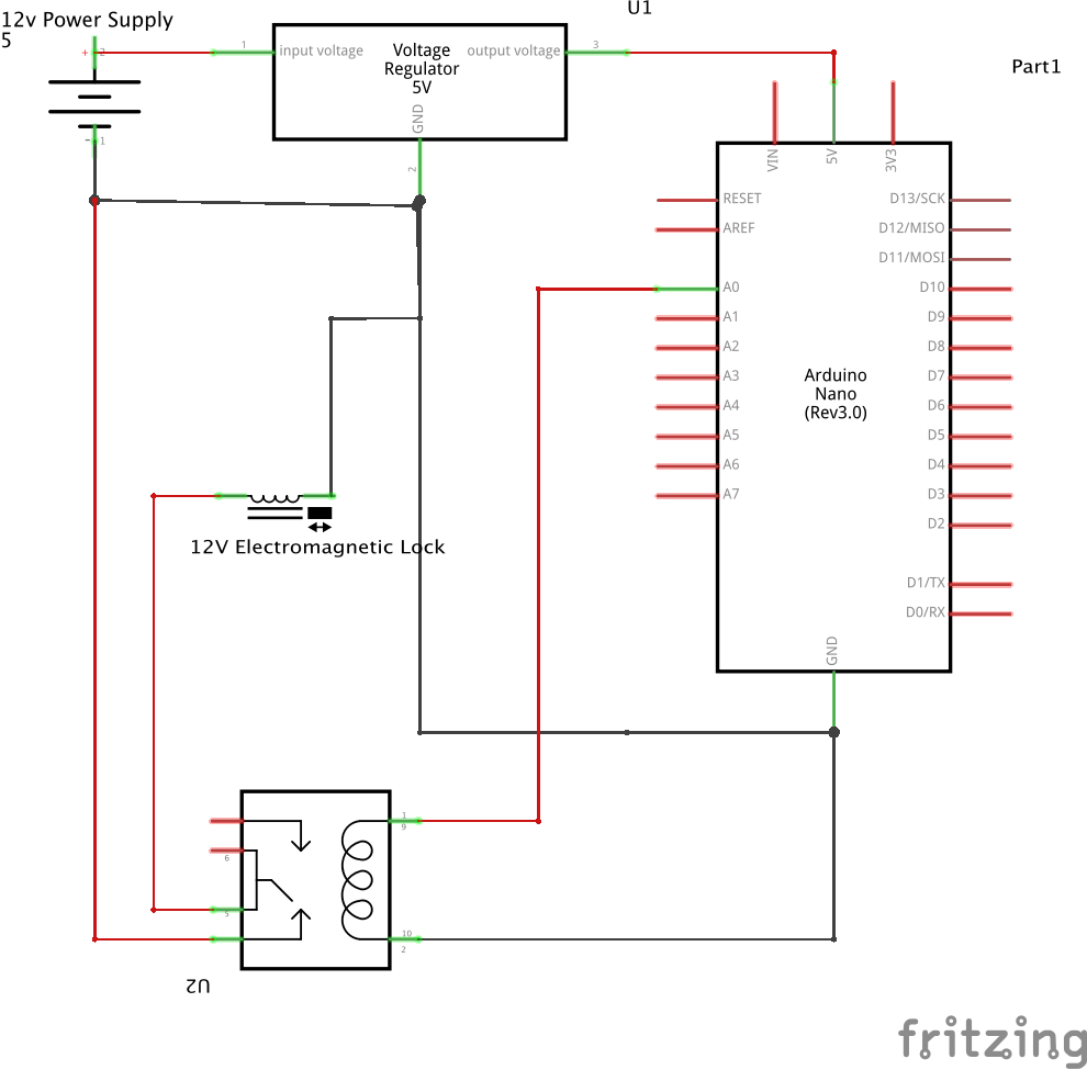
Note: I am using a relay module board that has all the necessary components for reliability such as the transistor before the coil and an optocoupler.

However, I've been having problems with this circuit.

The voltage regulator gets very very hot, even with a heatsink on it. When the relay disengages the lock, the arduino becomes unresponsive and requires a reboot to work properly again. The power supplies I am using are 12v 1000mA. And the electromagnetic locks I am using use up to 500mA when engaged.

My question is: is there a more reliable or easier way to power both the arduino and electromagnetic lock using the same power supply.

\$\endgroup\$
2
  • \$\begingroup\$ Shouldn't one side of the relay contact be connected to the 12V input voltage? This is probably an error in the drawing, otherwise the lock wouldn't work. \$\endgroup\$
    – Manu3l0us
    Commented Oct 20, 2017 at 6:39
  • \$\begingroup\$ You have my dream job. \$\endgroup\$ Commented Oct 20, 2017 at 9:03

3 Answers 3

3
\$\begingroup\$

As mentioned in other answers, swapping the 7805 linear regulator for a buck regulator would help with heat.

That said, I would believe there is no need for that: your use case should not consume so much power that even a linear regulator would get hot. The components you're powering off the regulator in the diagram would use less than 100mA in total, giving (12V - 5V) * 0.1 A = 0.7 W as maximum amount of heat the regulator would need to dissipate. Likely, when the relay is not energized, you would be using tenth of that at most.

So: check current usage of the different components with a multimeter to see where all that current is going.

  • The Arduino should consume in order of 15 mA, and there are many ways to reduce that even further: https://learn.sparkfun.com/tutorials/reducing-arduino-power-consumption
  • The relay board lists 65 mA as working current, and this should be much lower when the relay is not energized
  • Whatever you're using as the inputs to decide when to trigger the relay... Well, only you know what these are

There are many reasons why the Arduino might become unresponsive after triggering the relay, and it's not possible to tell certainly based on info you've given. Some possibilities:

  • The code you're running on it has no way of going from triggered state back to untriggered state. You need have a code path that turns off the relay and goes back to waiting for someone press the right buttons or whatever.
  • The electromagnetic lock consumes too much current when triggered (briefly or constantly), leading to Arduino input voltage dropping. If brief, this can be fixed with capacitor on regulator output (there should be one in any case)
  • Inductive voltage spike from the lock when it's turned off. A freewheeling diode helps here, i.e. a diode placed in parallel with the lock, the "wrong way" around, such that it should not conduct current. A voltage spike would be reverse to the normal working voltage, and would pass harmlessly through the diode.
\$\endgroup\$
2
  • \$\begingroup\$ Yeah I agree that the arduino should not be pulling that much current. Really the only other I/O devices that are connected are maybe 1-3 LEDs, push buttons, magnetic contact switches, or some microphone sensors. Can the current running through the 12v input of the voltage regulator(for the lock) be too high? \$\endgroup\$ Commented Oct 20, 2017 at 18:38
  • \$\begingroup\$ Also as far as my arduino hanging: I was having that issue when I was powering both arduino and lock from the same power supply. But when I used a separate power supply for the lock and kept everything else the same it fixed my issue. So the freewheeling diode idea sounds great. I thought the relay module that I was using would have that covered though. Can I have some more specifics on what kind of diode I should use and where exactly in the circuit it should go? \$\endgroup\$ Commented Oct 20, 2017 at 18:42
2
\$\begingroup\$

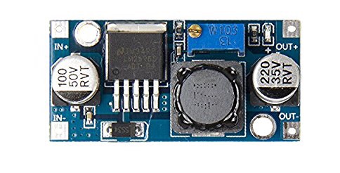
You should use a buck converter, which will give you a much higher efficiency. There are tons of options. Here’s one: LM2596

You’ll likely be better off buying one which is already laid out, like this: buck buck image

See also this question which discusses various buck/smps options, including some 7805 pin equivalent options (which @Manu3l0us's answer just reminded me of).

\$\endgroup\$
0
\$\begingroup\$

Like mentioned in the other response, a buck converter would help with the thermal issue. There are even drop-in replacements for the 7805, which is very convenient.

You may want to try adding a freewheeling diode to you electromagnetic lock. May be a voltage spike when turning it off causing your Arduino to hang.

\$\endgroup\$

Your Answer

By clicking “Post Your Answer”, you agree to our terms of service and acknowledge you have read our privacy policy.

Not the answer you're looking for? Browse other questions tagged or ask your own question.