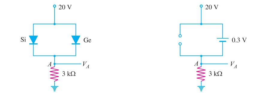
What if we decrease/increase the resistance 3kohm to a higher/lower value? Can someone explain this behaviour to me in a very simple way?  Will the current then flow through the silicon diode?
-
2\$\begingroup\$ You said it yourself: The silicon diode will never see 0.7 V because the germanium diode limits the voltage to 0.3 V. \$\endgroup\$– DampmaskinCommented Dec 1, 2017 at 13:41
-
\$\begingroup\$ what if the value of the resistor changes? \$\endgroup\$– ParanCommented Dec 1, 2017 at 13:46
-
2\$\begingroup\$ Then the current changes. \$\endgroup\$– DampmaskinCommented Dec 1, 2017 at 13:47
2 Answers
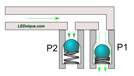
A very simple answer with another dodgy water analogy.
Figure 1. Parallel pressure relief valves. Relief pressure P1 < P2.
If we take these two pressure relief valves on a pneumatic or hydraulic circuit it should be clear that when the pressure rises enough to open the lower pressure valve that the pressure above the two valves can no longer increase (because it has been relieved) and P2 will not open. The parallel diodes with different \$ V_f \$, forward voltages, will behave in a similar manner.
I used this behavior in my solution to How to replace a green LED with a red one in a simple transistor switch? yesterday.
Note that if the pressure is high and the resistance of P1 is high enough relative to the downstream resistance then the pressure drop will increase to the point that P2 begins to open. This is analogous to reducing the resistor in your question to such a low value that very large currents flow through the germanium diode, the voltage rises due to its internal resistance and when it reaches 0.7 V the silicon diode will turn on. They'll both die quite quickly.
If it was 0.7 V across the Si diode, then it would be 0.7 V across the Ge diode, since they are in parallel. How much current do you think would have to flow through the Ge diode to achieve that voltage?
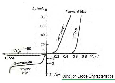
Here's a diagram:
(http://www.rfwireless-world.com/images/junction-diode-characteristics.jpg)
If we extrapolate around a voltage drop of 0.7 V for the Ge then I believe the \$I_F\$ for the Ge diode will be around 200 mA.
Is there 200 mA flowing through your Ge diode with 3 kΩ resistance?
No
So the voltage drop across the Ge diode will be around 0.3 V, what is the current for the Si diode at a voltage drop of 0.3 V?
Close to 0 ampere ≃ open circuit
So if you want both to conduct simultaneously, then you would decrease the 3 kΩ resistance until the point in the diagram above when both have current flowing.
I do recommend you to watch some youtube tutorials. Especially videos by Dave Jones. His videos were like a second teacher to me during my time at the university. And I also recommend using CircuitJS, my third teacher. Simulate, simulate, SIMULATE.
-
2\$\begingroup\$ "So if you want both to conduct simultaneously, then you would decrease the 3 kΩ resistance until the point in the diagram above when both have current flowing." Assuming the Ge one does not burn out first. +1 from me for reality though.. I often think they teach way too much "ideal", it leaves people with such a false sensor of how things actually work. \$\endgroup\$– Trevor_GCommented Dec 1, 2017 at 14:14
-
2\$\begingroup\$ Good answer, but I don't believe the question is too basic for the site - remember, the site's for enthusiasts as well as professionals and students :-) \$\endgroup\$– psmearsCommented Dec 1, 2017 at 17:49
-
\$\begingroup\$ Woaw, this is so cool, someone has a vendetta against me. Someone has downvoted my questions and answers. @downvoter, hello! This is equivalent to being called a hacker when you play online games. - Just fun. \$\endgroup\$ Commented Dec 2, 2017 at 12:28


