5
\$\begingroup\$

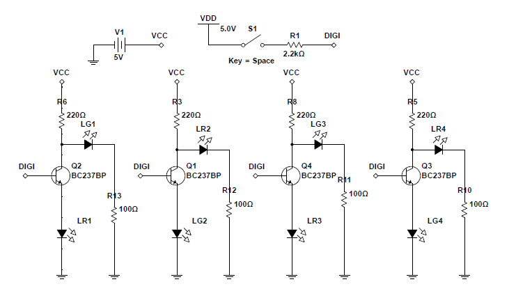
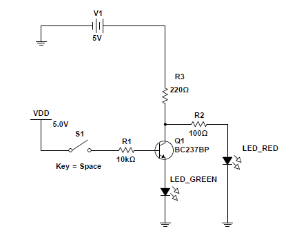
I am designing four traffic lights that I can control with a single digital switch. When the signal is 1, two traffic lights should be green, and the other two red, and they should reverse when the digital signal is 0. I'm using a simple transistor switch to achieve this:

enter image description here

This one works in the simulation, but I tried it on the breadboard, and it won't work properly unless I swap the green LED with the red one and vice versa. Otherwise, the red LED stays on regardless of the applied base voltage, while the green one stays off.

Moreover, the whole implementation doesn't work in the simulation. Only the first and the third gates switch properly. The second and the fourth ones have the above-mentioned issue:

enter image description here

Now, I'm aware that the red and green LEDs have different forward voltages (1.7V for red and 2.2V for green), but I don't know how to fix this problem.

\$\endgroup\$
3
  • \$\begingroup\$ It'll work for circuit one because the voltage at the anode of LG1 will dragged down below the turn on voltage for LG1 when Q2 is saturated. \$\endgroup\$
    – DiBosco
    Commented Nov 30, 2017 at 15:39
  • \$\begingroup\$ If you think about what the minimum voltage on the collector of Q1 can be, taking into account the voltage drop across the LED and the transistor, you will see why the red LED is always on. \$\endgroup\$ Commented Nov 30, 2017 at 15:56
  • 2
    \$\begingroup\$ "I'm using a simple TTL switch " no such thing.... \$\endgroup\$
    – Trevor_G
    Commented Nov 30, 2017 at 16:37

2 Answers 2

9
\$\begingroup\$

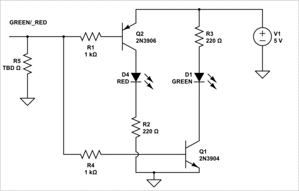
Using both NPN and PNP transistors is probably your best bet.

schematic

simulate this circuit – Schematic created using CircuitLab

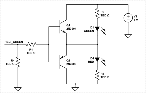
Or this way is more elegant.

schematic

simulate this circuit

ADDITION

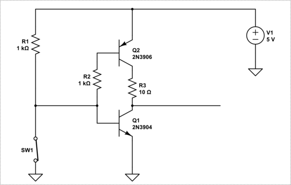
If you must drive this with a single pole switch, you should probably make the signal more active.

schematic

simulate this circuit

\$\endgroup\$
16
  • 1
    \$\begingroup\$ @MITURAJ there are numerous ways to do it.. two is my limit for freebies ;) Not sure what you mean though... I did it this way round so there is no shoot-thru and the LEDs are low enough Vf for 5V to cover the rail offsets. \$\endgroup\$
    – Trevor_G
    Commented Nov 30, 2017 at 16:08
  • 1
    \$\begingroup\$ OH wait... YOu said TTL,, you are just using a switch... \$\endgroup\$
    – Trevor_G
    Commented Nov 30, 2017 at 16:32
  • 1
    \$\begingroup\$ Maybe because the inputs to the transistors are floating at base. I think it has to be pulled up/down using resistors. \$\endgroup\$
    – Mitu Raj
    Commented Nov 30, 2017 at 16:33
  • 1
    \$\begingroup\$ @Trevor oh, it works now, thanks! but I'm still not sure by what you mean, isn't TTL just boolean logic with bipolar transistors? Isn't it the case here? (NOT gate) \$\endgroup\$ Commented Nov 30, 2017 at 16:44
  • 2
    \$\begingroup\$ @user2210558 A TTL signal is a very specific set of voltages and currents. What you have is just a floating line with a switched in pull-up. \$\endgroup\$
    – Trevor_G
    Commented Nov 30, 2017 at 16:47
9
\$\begingroup\$

Since the LEDs you are switching are different colours they have different forward voltages. We can do a nice trick with this.

enter image description here enter image description here

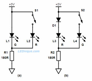
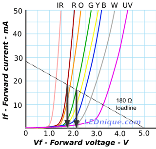
Figure 1. Switching between two LEDs with an N.O. contact and the load-line explanation. Source: 1 GPIO, multiple LEDs.

The intersection of the load-line graph shows us what voltage and current we can expect on each LED type with that value resistor.

  • In Figure 1a the green LED is on by default and the load-line shows that we can expect about 16 mA through it and 2.1 V across it.
  • If we switch on the red the forward voltage will drop to 1.75 or 1.8 V. At that voltage the green will pass only a couple of mA and should turn off or go dim.

If you want the red on by default then we add in D1 to induce a little more voltage drop. D1 + L3 = 0.7 + 1.75 = 2.45 V. When the switch is closed the green LED will cause the LED voltage to drop to 2.1 V and the red will go out.

If S2 is replaced with a logic output the voltage might not be sufficiently high enough so additional diodes may be required in the default leg.

enter image description here

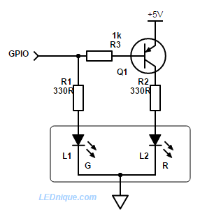
Figure 2. The advanced electronic solution uses a transistor! Source: 1 GPIO dual LED common cathode.

The GPIO in Figure 2 powers L1 directly when high. When low L1 turns off and Q1 turns on, powering L2. Note that the GPIO must be capable of driving L1 directly.

The links are to articles written by me.

\$\endgroup\$
0

Your Answer

By clicking “Post Your Answer”, you agree to our terms of service and acknowledge you have read our privacy policy.

Not the answer you're looking for? Browse other questions tagged or ask your own question.