1
\$\begingroup\$

I got some buttons and switches that are for automotive usage, so the LEDs inside are for 12V supply.

Is there a safe and efficient way to power these from an USB connector? I am planning to use an Arduino clone as a controller for these buttons and have the computer recognize it as an USB keyboard. Though, I would like to see the buttons LED on too, without adding an extra wire from an AC adapter just for the lights.

Would that be dangerous for the USB port on the motherboard? I do recall that the max current on USB is 500mA, although I have no info about how much power is needed to power the LED in the buttons (10 of them).

Is this possible and safe, or should I avoid to bump up the voltage of the USB port to power the LEDs?

\$\endgroup\$
5
  • \$\begingroup\$ Are the leds fed by a voltage dropping resistor calibrated for 12v - can you replace it with a resistor calibrated for the usb voltage? \$\endgroup\$
    – Solar Mike
    Commented Dec 13, 2017 at 5:50
  • \$\begingroup\$ Not sure, @SolarMike; how can I verify this? The button is self-enclosed; not sure I can take it apart to see if it has a resistor inside. Can I measure the resistor with the multimeter? \$\endgroup\$
    – rataplan
    Commented Dec 13, 2017 at 5:53
  • 1
    \$\begingroup\$ Just take it on faith that it does have a resistor inside. Measuring it is difficult if you don't have access to both sides of the resistor. Taking it apart may be easy depends on the switch. \$\endgroup\$
    – Passerby
    Commented Dec 13, 2017 at 6:39
  • \$\begingroup\$ If you don't have any info how much power is needed for your buttons, then do us a favor and measure it first before asking if it is "safe". Also, how do you know that these are LED-based, and not having an old lamp with 1 A current? \$\endgroup\$ Commented Dec 13, 2017 at 6:56
  • \$\begingroup\$ @AliChen, since the vendor that sell them did identify them as "12V LED" and they are used in automotive and marine, I thought they were standard. I work mostly with 3.3V devices, so it is my first dive into anything out of that realm. Which is also the reason why I did post instead of measure them first, but I get your point. \$\endgroup\$
    – rataplan
    Commented Dec 13, 2017 at 16:36

2 Answers 2

3
\$\begingroup\$

If you power the LEDs directly from the USB power they will draw less current, since the resistor inside is designed for an higher voltage. So you don't risk overloading the USB (those LEDs won't draw nowhere near 500mA, even at 12V).

The problem you will probably face is that at 5V they could be quite dim, or could even be off. But you could try and see if they light up sufficiently for your taste.

Disclaimer: I never took one of those apart, so I assume they have a limiting resistor inside (it's probably the cheapest option), but they could also have some sort of integrated constant current regulator chip instead (unlikely but possible). In other words, the LED itself could be one of those designed to be powered directly from 12V.

Anyway the best thing to do to test them is to hook them to a bench power supply set for 5V output and measure the current they draws using a multimeter.

If you don't have a bench power supply, an easy alternative is to put 3 new alkaline AA or AAA batteries (they are very common everywhere) in series: they have a nominal voltage of 1.5V, but if they are new they could source something more like 1.6V: you will end up with 3x1.6V=4.8V with which you could test your LEDs quite safely. Note that USB standard requires that the USB power lines are 5V±0.25V, so testing at 4.8V is quite reasonable.

BTW, what do you really mean with "... to bump up the voltage of the USB port..."?

If you plan to increase the voltage on the power lines of the USB bus with some additional circuitry, then DON'T DO THAT. That will damage your motherboard.

\$\endgroup\$
6
  • \$\begingroup\$ Thanks; so the issue is fundamentally that the resistor attached to the LED is draining the power, since it is set to deal with 12V, and the LED may not even turn on? In which case, should I go out and get LED that support 5V and throw away my current buttons? Or there is a way to still use these buttons somehow? Thanks! \$\endgroup\$
    – rataplan
    Commented Dec 13, 2017 at 6:33
  • 2
    \$\begingroup\$ 12 Vs - 3.5 Vf) / 0.02A = 425 ohms. At 5V and 425 ohms, its going to be more around 5mA instead of 20mA. It should still light up. \$\endgroup\$
    – Passerby
    Commented Dec 13, 2017 at 6:38
  • \$\begingroup\$ And it does light up; not super bright but I don't need it that bright. I have to chain 10 of them; I will try to see how many can I chain before they start to fade. Thanks! \$\endgroup\$
    – rataplan
    Commented Dec 13, 2017 at 6:42
  • \$\begingroup\$ @rataplan What do you mean by "chain" them? If you connect all the LEDs terminals to the USB supply, they'll end up in parallel, so technically they are not "chained" (this term recalls a series connection, instead). They won't start to dim: once you reach the 500mA limit on your USB bus the automatic overload detection of the USB controller on the motherboard will kick-in and will disable that USB port. \$\endgroup\$ Commented Dec 13, 2017 at 6:51
  • \$\begingroup\$ Sorry for the confusion; I did mean to do connect them in parallel; not in series so the term is probably incorrect. \$\endgroup\$
    – rataplan
    Commented Dec 13, 2017 at 16:39
2
\$\begingroup\$

You have three options, if you don't add an external supply. First, power wise. 10 leds at 20mA is 200mA. That's 1 Watt. Well within the "standard" 2.5W/500mA of USB. But most USB ports can provide more (not that you need them).

  1. Run them at 5V. The existing internal resistor will be (12 Vs - 3.5 Vf) / 0.02A = 425 ohms (or so). At 5V source and 425 ohms, I figure the Led would actually take around 5mA instead. This is still quite visible.

  2. Build a voltage doubler circuit. You would need a PWM signal for the circuit to produce the boost.

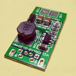
  3. Use an off the shelf/ebay 5V to 12V boost circuit. Simple, prebuilt. At 12V and 20mA and 10 Leds, that's 2.4W, plus the efficiency loss, more like under 3 Watts, well within what a 500mA USB port can provide. You will need transistors/fets to turn on/off the leds since you can't power them directly any more.

enter image description here

For 3, you can make it boost to 9V or 10V instead of 12V. This would bring down the current (and brightness) and lowers the power you need. An Led at 15mA is frankly just as bright as one at 20mA for most purposes.

\$\endgroup\$
1
  • \$\begingroup\$ Thanks for the response! I am going to connect the LED to a 12V source and see if the difference in brightness is enough to go for a boost circuit. The lesser I add on the circuit the better it is :) \$\endgroup\$
    – rataplan
    Commented Dec 13, 2017 at 22:25

Your Answer

By clicking “Post Your Answer”, you agree to our terms of service and acknowledge you have read our privacy policy.

Not the answer you're looking for? Browse other questions tagged or ask your own question.