0
\$\begingroup\$

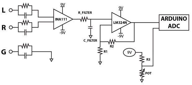
I'm pretty beginner here but I'm trying to implement this circular

enter image description here

The issue that I didn't find lm224 so i replaced it with lm324cd and I think it's not doing the same Electrical properties, this part taking charge of transmit electrical signals from over my head and transmit it to arduino, (Funny part) I can see electrical signal over my head, however I already done with this but it's seems that I've make some mistakes here, but I don't know really where.

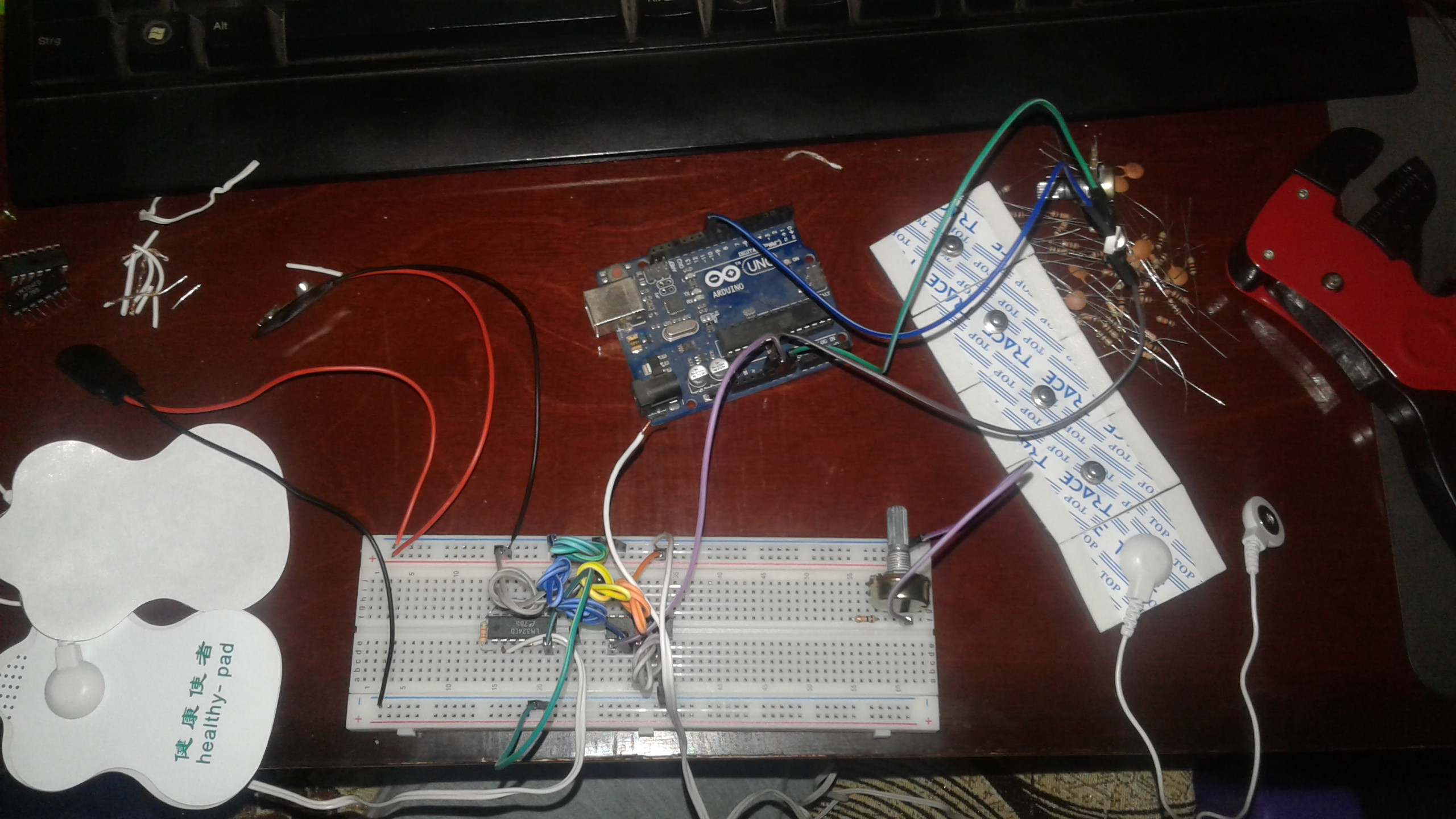
This the full circular (I'm afraid that it's not helpful so feel free to ask any question)

enter image description here

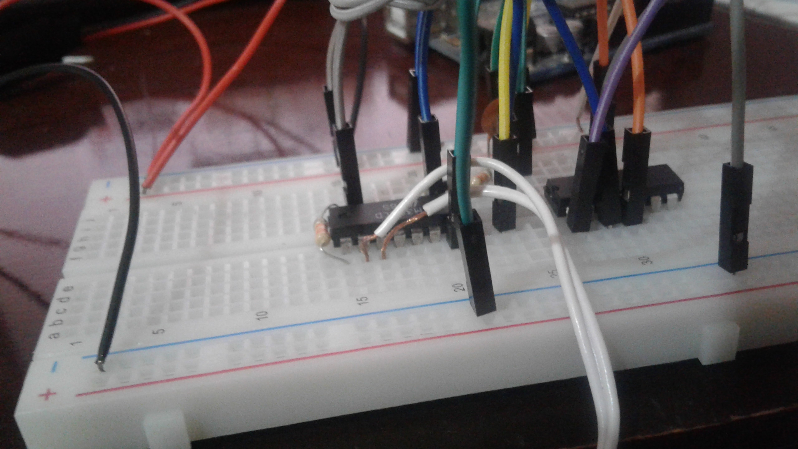
This zoom on the electrods I put on my forehead.

enter image description here

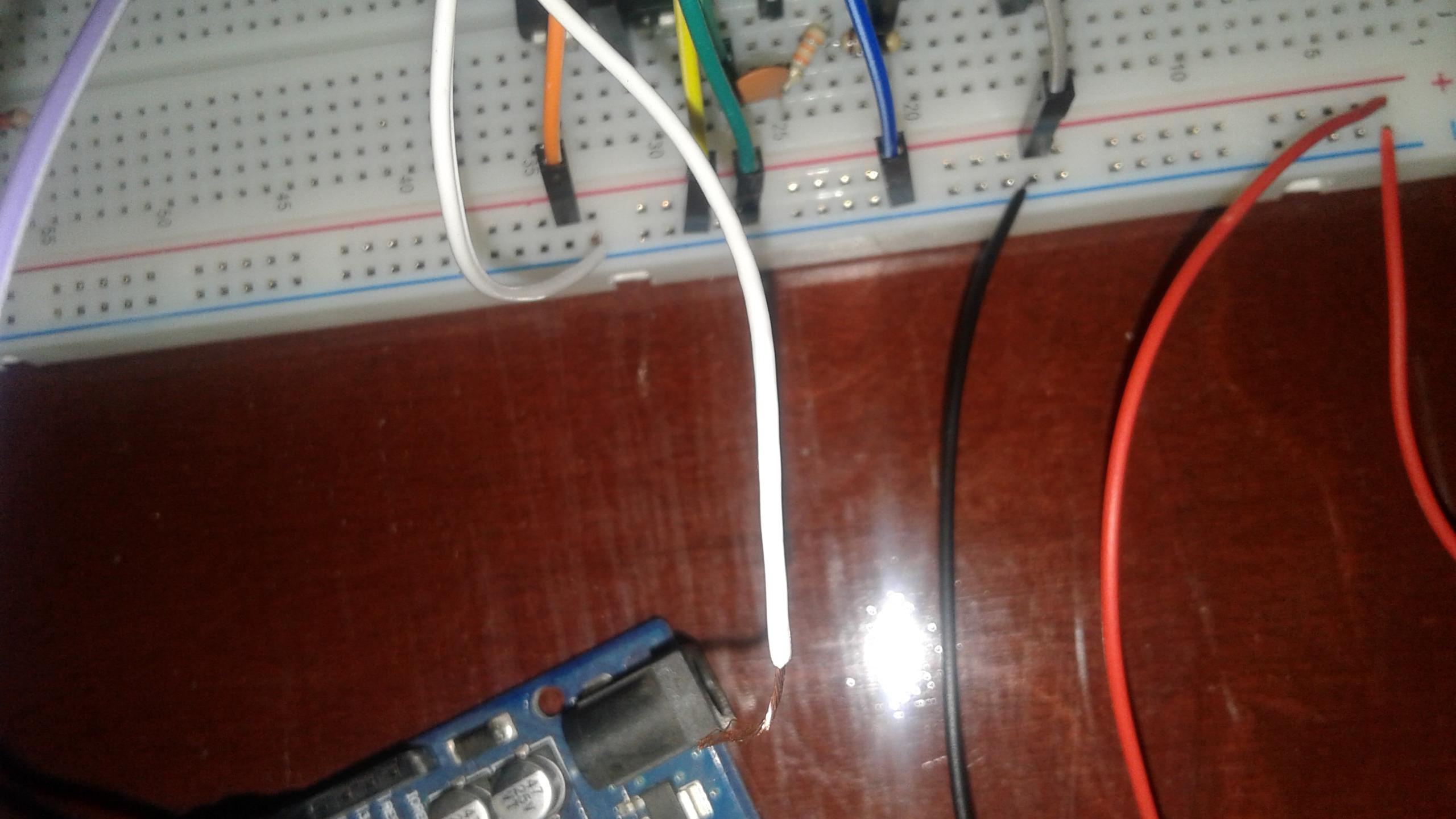
And this for the signal electrods I put on my front head.

enter image description here

Edit:

As a sensor, the solid gel electrodes have high input impedance and low output impedance: what this essentially means is that current can easily pass through downstream to the rest of the circuit (low output impedance) but would have troubling passing upstream back to my temples (high input impedance). This prevents the user from being injured by any high currents or voltages in the rest of my circuit; in fact, many systems have something called a patient protection resistor for additional protection, just in case. Many different electrode types exist. Most people suggest Ag/AgCl solid gel electrodes for use in EKG/EOG/etc applications. With this in mind, you need to look up the source resistance of these electrodes and match it to the noise resistance (noise voltage in V/sqrt(Hz) divided by noise current in A/sqrt(Hz) -- of my op amps -- that is how i choose the correct instrumentation amp for my device. This is called noise matching, and explanations of why matching source resistance Rs to noise resistance Rn works can be found online like here. For my INA111 that I chose And i replaced with lm324cd, the Rn can be calculated using the noise voltage and noise current of the data sheet like:

enter image description here

A possible specific question:

Can I replace LNA11 amp with any other amp? if yes what should I change in my circular ?

\$\endgroup\$
5
  • 2
    \$\begingroup\$ It would take me at least 10min to first convert your wiring diagram to a proper schematic and then to understand the job of the LM224. So, from my perspective, your wiring diagram is just a "cartoon" of the proper schematic, and unfit to serve as explanation to your question. Please convert it to a schematic diagram! (it's possible your wiring diagram software can do that). Also, your question should be closed under the reason that "repair (and replacement) question should be closed if OP doesn't show sufficient understanding of the circuit", UNLESS you explain what the LM224's job here is. \$\endgroup\$ Commented Dec 13, 2017 at 11:59
  • \$\begingroup\$ @MarcusMüller At least thanks for referring that, i will explain that. \$\endgroup\$
    – Ibrahim
    Commented Dec 13, 2017 at 12:02
  • 2
    \$\begingroup\$ @Ibrahim hm, your schematic doesn't agree with your wiring diagram: Your ground is directly connected to the clamp (which is probably a good thing), whereas your schematic shows there's a parallel capacitor/resistor in between. \$\endgroup\$ Commented Dec 13, 2017 at 12:07
  • \$\begingroup\$ @MarcusMüller Thanks, but I still don't know what should I do, I connected the small lamp in order to control it with electrodes but this fails, what my case this issue?, Is that because i replaced LNA111 with lm324? \$\endgroup\$
    – Ibrahim
    Commented Dec 13, 2017 at 12:14
  • \$\begingroup\$ This is merely a suggestion, but the TL072 op-amp is profoundly quieter than the LM324 series. It is good enough for 16 bit audio and has much higher input impedance. Also I would pay serious attention to @Marcus Muller's comments. VTC. \$\endgroup\$
    – user105652
    Commented Dec 22, 2017 at 3:17

3 Answers 3

5
\$\begingroup\$

INA111 is an instrumentation amplifier.
LM324 is an operational amplifier.

Those devices are NOT interchangeable. You need instrumentation amplifier, it is clear from your schematic.

\$\endgroup\$
2
  • \$\begingroup\$ Thanks, but in my country I can't find INA111 can i replace it with this AD620AN ? \$\endgroup\$
    – Ibrahim
    Commented Dec 13, 2017 at 13:51
  • \$\begingroup\$ Compare parameters in the datasheets. It depends what parameters are important for you or your application. \$\endgroup\$ Commented Dec 13, 2017 at 14:40
4
\$\begingroup\$

The issue of whether an LM324 can replace an LM224 is best answered by looking at the data sheet. But let me save you the trouble - in this circuit it will work just as well.

The INA111, however, is a different thing entirely - it's an FET input instrumentation amplifier (effectively three op amps wired together in a single package). An LM324 will definitely NOT work in place of that.

\$\endgroup\$
2
  • \$\begingroup\$ Thanks, but in my country I can't find INA111 can i replace it with this AD620AN ? \$\endgroup\$
    – Ibrahim
    Commented Dec 13, 2017 at 14:29
  • \$\begingroup\$ Compare the data sheets and see what the differences are. \$\endgroup\$
    – Finbarr
    Commented Dec 13, 2017 at 14:33
2
\$\begingroup\$

Well, you can certainly replace an INA111 with an LM324. It may or may not work as well as you need, but that's a different story.

As has been mentioned, an INA111 is an instrumentation amplifier, not an operational amplifier. What has not been mentioned is that instrumentation amps are made from op amps. Find the data sheet for the INA111 on the web. On the first page you will find the equivalent circuit, which employs 3 op amps and a bunch of resistors. There is nothing preventing you from rolling your own version using 3 of the 4 op amps found in an LM324 or LM224.

Of course, the LM324 isn't a very good op amp, especially in terms of things like input bias currents and offset voltages, while the INA111 does use pretty good amplifiers. Plus, building an instrumentation amp with good performance also requires things like well-matched and precise resistors, so your home-brew instrumentation amp will likely not work nearly as well as an INA111. Whether that is good enough is an entirely different matter.

With that said, I suspect that you have really messed up your circuit. Particularly, I think you have simply replaced the INA111 with a single section of an LM324. Trust me, this won't work. If you've done what I think you've done, you have no feedback, and the output of the "new" LM324 is stuck at about plus or minus 7 volts. You need to learn far more about circuit operation before you can try making substitutions.

Among other things, you have not recognized that the schematic you have used is incomplete - the INA111 symbol does not show the gain connection which must be made, so there is no way of knowing what gain it is operating at.

So, first things first. It has been mentioned that you have not provided a schematic of what you have built. You responded by providing pictures of your breadboard. Look - you are avoiding the issue. Stop it. A picture of your breadboard is not a schematic and never will be. Use the schematic editor - edit your post and select the icon with the diode and resistor, or just hit ctrl-m. Now make a schematic of exactly what you are doing. Stop making life hard on folks who want to help.

\$\endgroup\$
0

Not the answer you're looking for? Browse other questions tagged or ask your own question.