5
\$\begingroup\$

I want to detect logic of the mains supply (230VAC, 50Hz) and feed the output of HCPL-3700 into ATmega16L. I read through the datasheet but could not understand how to calculate the resistor values. Does anyone have an idea of how to go about doing this?

EDIT 1

I am referring to application note on HPCL-3700, page 5 under AC Operation With No Filtering

Assuming 60% criterion, 230 x sqrt(2) x 60% is 195V. choosing closest whole value of 200V instead of 195V.

Rx = (V+ - VTH+) / ITH+ = (200V - 5.5V) / 2.5mA = 38.9 Kohms.

choosing round figure of 40 Kohms for Rx. I can use two 22 Kohm resistors.

Calculating power dissipation in 22 Kohm resistors
P = (I*I) * R
= (4.4mA * 4.4mA) * 22K (where 4.4mA is Iin)
= 426 mW

So, choosing 22 Kohm resistors with 500mW power rating.

How does this answer look? I think I'm wrong because there are few things that still don't make sense.

\$\endgroup\$
5
  • \$\begingroup\$ What do you mean by "logic" of mains supply? \$\endgroup\$
    – miceuz
    Commented Jun 25, 2012 at 6:25
  • \$\begingroup\$ It's not clear to me why you suddenly want to use a 4 times more expensive optocoupler, after all the trouble we took to calculate for the cheaper SFH620A. \$\endgroup\$
    – stevenvh
    Commented Jun 25, 2012 at 10:01
  • 1
    \$\begingroup\$ I don't know where you got the 4.4 mA, but the power calculation is wrong. You have 230 V across 44k, that's 230\$^2\$/44000 = 1.2 W, so each of the 22k should be 0.6 W. I would take at least 0.75 W. \$\endgroup\$
    – stevenvh
    Commented Jun 25, 2012 at 10:07
  • \$\begingroup\$ i know man, but my supervisor wants me to take a look at this optocoupler instead of the previous one. He says its 'better' because of it has a bridge rectifier. I am pretty pissed too \$\endgroup\$ Commented Jun 25, 2012 at 10:08
  • \$\begingroup\$ Uh-oh, supervisors :-(. You could tell him that the other one doesn't need a bridge rectifier because it handles both halves of the phase by the two LEDs in antiparallel. Does the same thing for 2.50 dollar less. \$\endgroup\$
    – stevenvh
    Commented Jun 25, 2012 at 14:08

1 Answer 1

5
\$\begingroup\$

The datasheet should have been a lot more clear on this. The only relevant information on the output pull-up I could find was on page 3:

Logic low output voltage = 0.4 V maximum, at 4.2 mA
Logic high output current = 100 \$\mu\$A maximum

That last value must be the off-leakage current, but it's very high. It would mean that a 1 kΩ pull-up resistor would drop 100 mV, a 10 kΩ would give an unacceptable 1 V drop. I would stick to 1 kΩ.

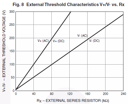
For the input resistors you need figure 8 of the datasheet.

enter image description here

This shows the threshold values for the input voltage hysteresis as a function of series resistance. For instance, at 40 kΩ the levels are 50 V and 100 V. That means the output goes low if 100 V is exceeded, and high again if the input voltage goes below 50 V. At 230 V AC the output will be low between 18° and 171° of a half cycle, that's a 85 % duty cycle.

\$\endgroup\$

Your Answer

By clicking “Post Your Answer”, you agree to our terms of service and acknowledge you have read our privacy policy.

Not the answer you're looking for? Browse other questions tagged or ask your own question.