I want to characterize the frequency inaccuracy of several silicon oscillators over temperature to see which one will work best in my end application. If I populate the oscillator on a bare-board and solder a coaxial pig-tail to the trace/GND will that suffice? Since the oscillator is designed to drive a high-impedance IC clock input, will it be able to drive the low (50Ω) impedance of the spectrum analyzer? Do I need to add some special matching, DC-block, or bypass network? I'd like to introduce the least amount of extra components possible as I'll have to take them into account in my measurements as well.
-
\$\begingroup\$ 1. A datasheet for your oscillator would help us answer your question. 2. If you're just measuring frequency accuracy, why would you expect external filters to affect the measurment? 3. If you expect an external filter to affect the measurment, why don't you expect a drastic change in the load to affect the measurement? \$\endgroup\$– The PhotonCommented Jun 28, 2012 at 15:42
-
\$\begingroup\$ @ThePhoton - 1.I knew someone would ask, but I tried to keep it general since I'll be testing multiple oscillators. I'm hoping to avoid the "here's your circuit for this specific part" solution. \$\endgroup\$– Joel BCommented Jun 28, 2012 at 16:11
-
\$\begingroup\$ @ThePhoton - 2. I didn't say I expect external components to affect the measurement. For extra components I said I didn't want to "take them into account" which seemed like a nicely ambiguous way to say "There could be frequency effects (which are probably negligible)" but also accomplishes my real intent that "There's a complete circuit for this and there's a minimal solution which will get me decent-enough results for evaluation, I want the latter". Thus saving this question from a trip to meta or the wrath of Olin. \$\endgroup\$– Joel BCommented Jun 28, 2012 at 16:15
-
\$\begingroup\$ OK, but is your oscillator buffered or not? What is the drive capability of the buffer? The answer to your question "will it be able to drive the low impedance...?" depends entirely on details that will only be found in the datasheet(s). \$\endgroup\$– The PhotonCommented Jun 28, 2012 at 16:16
-
\$\begingroup\$ What sort of measurement do you want to make? Short-term drift, long-term drift? \$\endgroup\$– mngCommented Jun 29, 2012 at 15:13
2 Answers
the oscillator is designed to drive a high-impedance IC clock input
In this case, you will want to add a buffer chip to be able to drive the 50 Ohm coax and the spectrum analyzer input. The appropriate chip depends on what type of load the oscillator is designed to drive (TTL, CMOS, ...?), the frequency, the available power supply voltages, etc.
Possibly you could use a transformer instead of an IC buffer to impedance-match the cable, but the buffer has the advantage of providing exactly the type of load the oscillator is designed for (an IC input).
Incidentally, if you want to measure the frequency accuracy of your oscillator and not other parameters, a frequency counter will give you a more accurate measurement more quickly than a spectrum analyzer. But it will still likely have a 50 Ohm input unless you're working at very low frequencies (below 1 MHz?).
Remember that spectrum analyser can work without cable, just with antenna ?
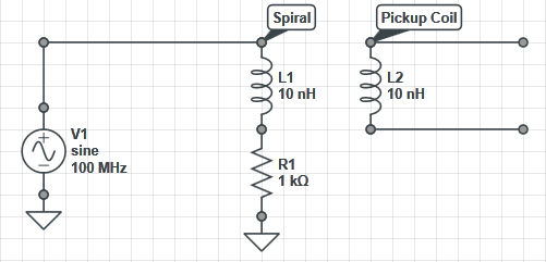
You can make an air core ("styrofoam core") transformer: draw a 10-15 turns spiral on a board and terminate it with high-Z load. Glue an insulating pad on top of it and slap a 3-5 turns of insulated solid wire soldered to BNC connector. Cover everything with pile of glue.
Connect spectrum analyser to this pickup coil and you are done with impedance/overload/grounding problems.

