0
\$\begingroup\$

I am a complete novice with anything beyond simple wiring of guitar effects and kits. I have a unit, a Roland GR-55, that has a momentary switch built-in. I want to trigger this switch with a separate unit (Boss MS-3) that contains its own momentary switches, and which allows me to "assign" those switches via a 1/4" TS type jack. These switches work like regular passive momentary switches. If I want to control the GR-55 switch externally via this second unit, I need to isolate the circuits so as not to fry the CPU in the GR-55 in case of some ground fault or other issue I might not know about.

I am looking at this relay module: HiLetgo 12V 1 Channel Relay Module With OPTO Isolation Support High or Low Level Trigger, $4.99

I think I understand SOME of how I might be able to use this in this particular situation: use the internal 9V DC power of the GR-55 to feed the DC +/- on the relay. Connect the two leads of the momentary switch in the GR-55 to the relay "open" and "common" contacts. This keeps the logic of the GR-55 isolated from the external switching system and the 9v supply.

What I do NOT understand is this: there is one contact on the transmit side that accepts a high or low level signal, but a simple momentary switch is simply a passive loop connector. Is there any way to use this kind of pre-fab circuit with a passive switch, or does it REQUIRE a second powered circuit/signal to trigger the relay?

If this board will not work, is there any other simple solution to this problem that would not require my having expertise in the area?

\$\endgroup\$
2
  • \$\begingroup\$ I think you can easily do what you set out to but it is very hard to help you without more information, maybe try to post a diagram or a drawing or some pictures? \$\endgroup\$
    – user173292
    Commented Jan 3, 2018 at 21:22
  • \$\begingroup\$ I'd simply use a reed relay for this application. I suppose you intend to modify the GR-55. Just hook the reed relay's contacts across the current GR-55 switch contacts. (No removal of the manual switch required.) There will be a tiny coil wrapped around the reed relay. This coil needs to be energized by the MS-3's momentary 1/4" jack. You'll need to source power for that (small battery or else find something in the MS-3.) Reed Relay Description. These things are very tiny and will fit anywhere. \$\endgroup\$
    – jonk
    Commented Jan 3, 2018 at 23:08

1 Answer 1

0
\$\begingroup\$

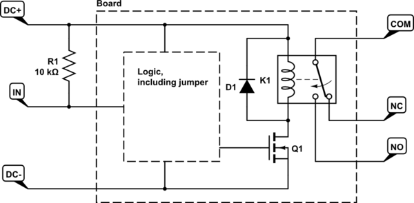
I think you're overcomplicating things with the pre-fab, does-all relay module. That module is probably this:

schematic

simulate this circuit – Schematic created using CircuitLab

And to answer your original question, the part you're missing is R1 to bias it towards whichever DC rail you connect it to. I've drawn it as a pull-up because of tradition, in which case the controlling switch would go between IN and DC-.

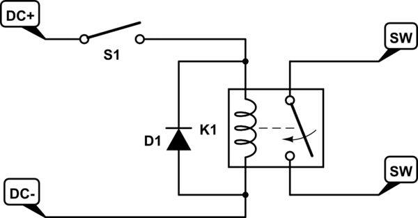
But all you really need is this:

schematic

simulate this circuit

If the controlling switch S1 controls to the negative side instead, that works too; the order doesn't matter as long as you know it and design accordingly.

The relay itself provides the isolation, but I'm not convinced that you actually need it:

  • If the controlled switch and the controlling switch both switch to ground (see the note on my first schematic) and they both have the same ground, then you only need one wire in theory, straight across. The return current would flow through the common ground, which would technically cause a slight error in the ground voltage, which is what causes ground loop noise...but only if that current has audible frequencies in it. This is DC, which you can't hear and the equipment should reject anyway. Maybe it clicks when you press and/or release it, but that would be all.

  • If the controlling switch is already isolated, then you don't even have that problem. Just run two wires straight across and be done.


About the diode, D1, in both schematics: The circuits may work without it...for a while. But because you can't stop the current instantly through the relay coil, being an inductive device by necessity, it will generate whatever voltage it needs to keep that current flowing until the energy dies away. D1 provides a path to do that without requiring crazy high voltages (hundreds, maybe thousands of volts, briefly) that may eventually destroy a switch (and certainly a transistor, Q1), which the relay will happily do if that's what it takes to keep the current flowing. Any old diode will do, provided that its maximum reverse voltage is more than the relay's operating voltage.

\$\endgroup\$

Your Answer

By clicking “Post Your Answer”, you agree to our terms of service and acknowledge you have read our privacy policy.

Not the answer you're looking for? Browse other questions tagged or ask your own question.