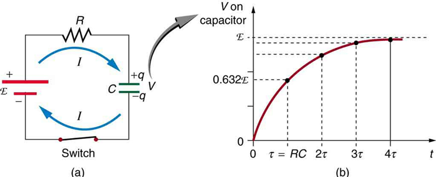
In an RC circuit the fully charged capacitors behave like an open circuit, the inductors, in one of type RL, are taken as short circuits.
3 Answers
They behave according to the capacitor and inductor equations. Here they are:
$$ i_c(t) = C\frac{dv_c(t)}{dt} $$
$$ v_l(t) = L\frac{di_l(t)}{dt} $$
where
- \$i_c(t)\$ is the current through the capacitor with capacitance \$C\$ at time \$t\$
- \$v_c(t)\$ is the voltage across the capacitor with capacitance \$C\$ at time \$t\$
- \$i_l(t)\$ is the current through the inductor with inductance \$L\$ at time \$t\$
- \$v_l(t)\$ is the voltage across the inductor with inductance \$L\$ at time \$t\$
Notice the \$\frac{d}{dt}\$ terms are precisely the "when they are changing" factors you're concerned with.
I assume you are talking about the moment when current is flowing into or out of a capacitor or inductor.
I won't dwell too much into the different force fields and complex voltages / currents / impedances. So I will be more or less "loosely speaking" throughout this entire answer.
Apart from the fact that both of these components change the phase of the current with respect to the voltage, they behave like a resistor, in the sense that they have an impedance and energy can be put into them.
At any given time they have an impedance, this means that if you make a simple RC LP filter, in the time domain when you apply 5 V at the input of that filter. The impedance of the capacitor will take on the values of 0 Ω all the way to \$\infty\$ Ω as it charges up.
The same thing happens during discharge, at first it's 0 Ω and then the more it discharges the higher the impedance becomes.
For the inductor it's the reverse.
If you take out a capacitor out from the circuit when it has reached 2.5 V in the above RC LP example, then in your hand you will have a 2.5 V voltage source. You can stick the contacts onto your tongue and feel a nice buzz (I've done it with 3.3 µF charged to 24 V, tingles really much). If you change the 5 V input to 2.5 V input and stick your charged capacitor in there, then it will behave like it has \$\infty\$ Ω.
If you however do the exact same thing but replace the capacitor with an inductor then things will be very different. In this case it's a RL HP filter. So let's say that you the R is 5 Ω and your input is 5 V. This means that the inductor can charge up to 1 A. Let's say you let it charge up to 1 A and then take it out. All the electrons inside the coil of the inductor will keep their momentum and gather at one end of the wire that makes up the coil. So at one end of the coil there's a major abundance of electrons. At the other end of the coil there's a major lack of electrons. This means there's a very high voltage between the ends. If it's high enough you can make a really huge spark like lightning between the ends. But you will not be fast enough to take it out of the circuit with your hands before the electrons has crashed into the end of the wire. So you will see small shocks between the coil wire and where it just was.
If you however let the coil charge up to 0.5 A instead, when it's half way to 1 A. And you then take it out of the circuit, the only difference here is that the voltage will be much less and you might not see any sparks. In both the 1 A case and the 0.5 A case, after a couple of seconds there will be 0 A flowing and 0 V across them. In the capacitor case there were still some voltage across it but no current.
So I said before that with the coil the momentum of the electrons keeps them going forward, that resembles a current source. And that's exactly what you got.
Hmmm, maybe I'm just mumbling random stuff. But hey, your question consists of 2 sentences, so can you blame me? I even introduced this answer with the 2 words "I assume".
There are two fundamental equations.
- For a capacitor, I = C dv/dt and,
- For an inductor V = L di/dt
If you don't know what dv/dt or di/dt is this answer might need some prior research before proceeding further.
So, for a capacitor, that formula tells you that the current flowing into it is capacitance multiplied by the rate of change of voltage applied with respect to time. If the capacitor is being discharged then dv/dt is negative and current is negative i.e. flowing from the capacitor.
For the inductor, the formula tells you that for a fixed applied voltage across the terminals, the current will rise (dv/dt) at a rate of V/L.
In an RC circuit the fully charged capacitors behave like an open circuit
They appear to be open circuit but if you try and extract current or inject current then they can be seen to be a substantial source of energy.
How do these elements (capacitors and inductors) behave when they are charging in a circuit with a DC source?
You will find a similar equation for L when being charged up to a limiting current. Try googling it.


they are not fully charged or discharged in a circuit... do you meanthey are not fully charged or not fully discharged in a circuit? \$\endgroup\$