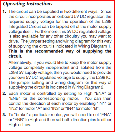
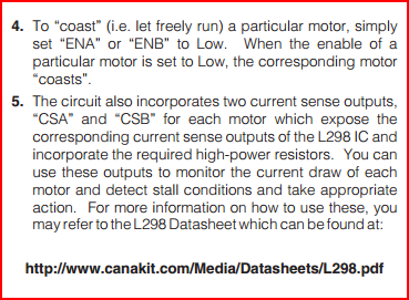
The answers are in the datasheet:


Points 3, 4 and 5 tell you what the pins do. INx are digital inputs for controlling motor direction. ENx are digital inputs for enabling each motor. The CS pins are for current monitoring purposes. There is a small resistor (e.g. 0.5 ohms in this case) between this pin and ground, so the current will be translated to a voltage at the CS pin (e.g. 1A * 0.5 ohms = 0.5V)
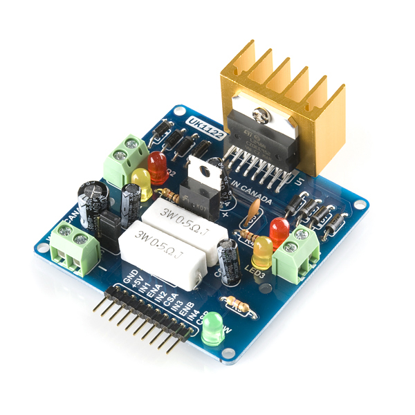
You can see the two large 3W, 0.5 ohm current sense resistors clearly in the picture below:

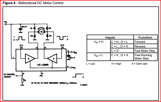
Here is an example from the L298 datasheet:

The quality isn't very good, sorry. Note this shows only 1/2 of the LM398. Hopefully you can see the resistor at the bottom left, with a tap off to "control circuit" (e.g. current can be controlled if desired, and monitored for overcurrent)
The truth table gives the same info as points 3, 4, 5. C and D equal IN1 and IN2 (or IN3, IN4 for the other half) Ven equals EN1 (or EN2..) and the pin with the resistor is CSA (or CSB)
Hope this all makes sense.


