3
\$\begingroup\$

My understanding is that SEPICs, Cuks, and Zeta converters all provide a stable output voltage despite an input voltage that can vary either above or below what is desired. The SEPIC and Zeta maintains the same polarity, while the Cuk reverses the polarity but by making an isolated version you can maintain the polarity.

Given an application that benefits from these intrinsic properties why might I consider one over the others?

\$\endgroup\$
4
  • \$\begingroup\$ I've found an good answer in this article, consider reading it: ieeexplore.ieee.org/stamp/stamp.jsp?tp=&arnumber=7437823 \$\endgroup\$
    – Jakey
    Commented Jan 29, 2018 at 15:57
  • \$\begingroup\$ There must be many articles on google about this - what have you found that partially explains an answer to you? \$\endgroup\$
    – Andy aka
    Commented Jan 29, 2018 at 16:23
  • \$\begingroup\$ electronicsweekly.com/blogs/engineer-in-wonderland/… was good at giving me a start. But most articles are looking only at one type and not actively comparing benefits and drawbacks. \$\endgroup\$
    – CraigC
    Commented Jan 29, 2018 at 18:27
  • \$\begingroup\$ SEPIC can regulate Vout when Vin is above, below or the same. This is the main reason I choose SEPIC. \$\endgroup\$
    – Oliver
    Commented Aug 10, 2018 at 14:13

2 Answers 2

7
\$\begingroup\$

SEPIC and ZETA are able to step up AND step down, similar to 2sw/4sw Buck Boost; Cuk = inverting SEPIC is able to invert a voltage, similar to inverting Buck Boost.

For smaller power range <30W those topologies are beneficial, because a boost controller (SEPIC, Cuk) or a buck controller (ZETA) w/ a single driver is cost effective; so power stage itself works w/ a SINGLE FET and a SINGLE rectifier, cost effective too - compared to 2sw/4sw Buck Boost needing four silicons. Cuk needs an additional OpAmp to turn negative output into positive feedback for the controller.

SEPIC has continous input current, so less reflected ripple, less conducted emissions; ZETA has continous output current, less ripple to the load. Cuk has continous input AND output currents, well suited for sensitive loads and sensitive sources, i.e. radio apps.

Google for some of my designs "PMP10081" = SEPIC, "PMP30373" = Cuk, "PMP10070" = ZETA, "PMP10214" = 4sw BuckBoost; figure out my name and you'll find some articles, too... have fun at the world of power electronics.

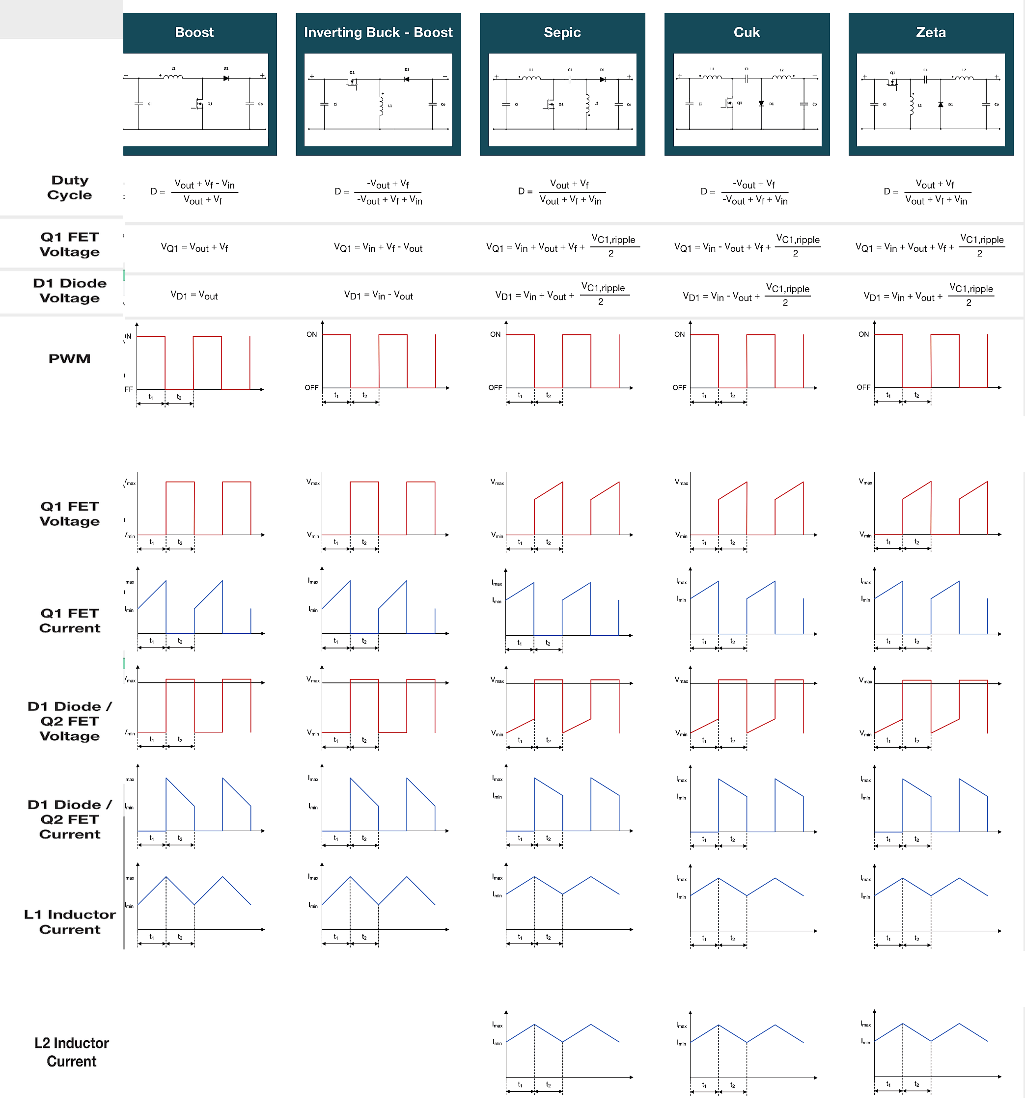
\$\endgroup\$
1
  • \$\begingroup\$ Zeta is the inverse of SEPIC, not Cuk, which is very unique and has no inverse that I know of. I will try to come back and add the reference. \$\endgroup\$ Commented Jan 27, 2022 at 21:25
1
\$\begingroup\$

It depends more on your component selection.

It's a good topic for a book based on all the choices below; (Hence too broad to answer, but here's a kickstart )

Zeta

http://ww1.microchip.com/downloads/en/AppNotes/01467A.pdf
http://www.ti.com/lit/an/slyt372/slyt372.pdf
http://www.linear.com/solutions/4993

Some differences between these topologies are:

  • SEPIC and Cuk converters became from the boost converter, and ZETA converter from the buck-boost converter.
  • The ripple current in the load is greater for Cuk and ZETA converters than SEPIC, because the SEPIC converter has an inductor L2 that smooth the current spikes.
  • The switch of SEPIC and Cuk converters is a N channel MOS transistor that needs a Low Side driver when the ZETA converter has a P channel MOS transistor that needs a High Side driver.

See TI.com for starters.

It also depends on your critical specs, priorities and experience. ( as with any design)

  • Cost , Parts count, size, qty
  • Performance ( efficiency, temp rise, EMI , load regulation, ripple current reduction, isolation, continuous current mode, stress on components... are just a few reasons.
  • Reliability , Stress Factors ( from above Specs, results and design choices)

Example of Buck mode

enter image description here

\$\endgroup\$
3
  • \$\begingroup\$ All three have the same waveforms, while the SEPIC and Zeta have the same equations. The Cuk is subtracting Vout while the other two are adding it, which makes it less stressful for the Diode and FET. Are their any other components that have lower/higher voltage/current ratings? \$\endgroup\$
    – CraigC
    Commented Jan 29, 2018 at 18:33
  • \$\begingroup\$ Yes but that depends on in - out differences and ratio or specs. Consider the application too and component ESR total effects on Zout, Zin and stability. PV regulator method should be ICT method for better performance \$\endgroup\$
    – D.A.S.
    Commented Jan 29, 2018 at 18:51
  • \$\begingroup\$ Also consider efficiency when |Vin|-|Vout| is near 0. And also consider 2 FET switches instead of 1 + diode. for synchronous ZVS \$\endgroup\$
    – D.A.S.
    Commented Jan 29, 2018 at 18:58

Your Answer

By clicking “Post Your Answer”, you agree to our terms of service and acknowledge you have read our privacy policy.

Not the answer you're looking for? Browse other questions tagged or ask your own question.