0
\$\begingroup\$

I want to discharge a capacitor (0.47μF) through a led (red led: 2V, 15mA) but I want the discharge remains for a while e.g. 60s or 30s. I charged the capacitor with 10V then I calculated the resistance's value (533Ωhm) to have 15mA current but the discharge was very quick.The led lighed up for just a moment. I know that if I put a bigger capacitor the discharge will remain for a longer time. But, I want the specific capacitor to use with 0.47μF capacitance and if it is possible to change the resistance.

So I try to use the function V(t)=Vo*e^(-t/RC) to calculate the RC.

The values for the function are: t=60s Vo=10V and V(t)=2V as a result RC=186,45s

So, if I put in the function C=0.47μF, the value of the R is calculated 79MΩhm but I can't succeed 15mA current with this resistance.

As a result the led never light up! Could you recommend a way to have the above capacitor but with a little bit longer discharge?

\$\endgroup\$
1
  • 1
    \$\begingroup\$ The cap only has so much energy to light the LED with 15mA for that time. If you want longer time, supply more energy or use less energy per time. \$\endgroup\$
    – PlasmaHH
    Commented Feb 14, 2018 at 15:10

2 Answers 2

8
\$\begingroup\$

No. To quote a famous actor "It's physics Jim". Your formula has already told you that it is not possible There is nothing we can say which changes that.

You can gain a bit by using a more sensitive LED, some work good at 0.5mA (I thought you 15mA was way over the top anyway). But that is where it stops.

\$\endgroup\$
1
\$\begingroup\$

On the one hand, you want a resistor of 533 ohms.
On the other hand, you want a resistor of 79000000 ohms.

That's quite a span to overcome.

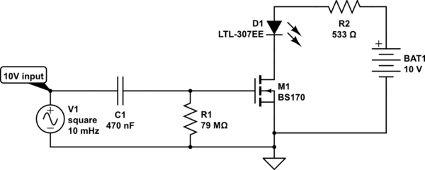
It seems that a small MOSfet transistor would be useful to span that difference. Its high-resistance gate has resistance larger than 79 Megohms to ground. And its low-resistance drain-to-source path is much lower than 533 ohms. So a circuit like this is possible:

schematic

simulate this circuit – Schematic created using CircuitLab When C1's input side rises to +10V, the MOSfet turns on, and 15 mA flows through R2 and the LED.
C1 will initially raise M1's gate voltage to +10V, but then start discharging through that very large R1, toward zero volt. After a time, M1's gate voltage will have dropped to about +2V, and M1 will start to turn off.

This is a conceptual circuit to show how the RC time constant of C1 x R1 could be used to stretch the ON period of a relatively high-current LED. In practice, that 79M resistor on the gate may be too large - the leakage current of that BS170 MOSfet may interfere.

\$\endgroup\$

Not the answer you're looking for? Browse other questions tagged or ask your own question.