The direct link to the datasheet is LEM CV3-1000.

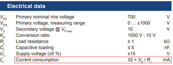
Figure 1. From the datasheet.
Let's figure out the worst case current consumption:
- If \$ R_L \$ is 1 kΩ (the minimum allowed) and \$ V_{PN} \$ is +700 V then the current consumption will be \$ I_C = 32 + \frac {700}{1000} = 32 + 0.7 = 32.7\ \mathrm{mA} \$. (At -700 V it will be 32 - 0.7 mA.)
- The voltage out will be given by the 1000:10 conversion ration and so will be +7 to -7 V.

simulate this circuit – Schematic created using CircuitLab
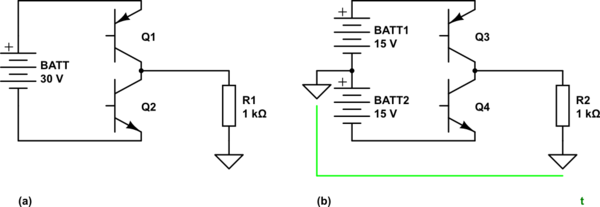
Figure 2. (a) What you are proposing. (b) What is required.
- In 2(a) there is no return path for R1 so the circuit can't work.
- In 2(b) there is a return path.

simulate this circuit
*Figure 2. A work-around."
If you are stuck the circuit of Figure 2 should work. Assuming that the device will draw the same current on the positive and negative supplies there is probably little current on the 0 V pin other than the return current from R1. Set R3 to give 20 mA through D1 and you should be OK. Confirm that the voltage between 0 and -15 V is stable at both +700 and -700 V on the input.
Pay attention to the 5% tolerance on UC. A dual power supply would be a better option. Single to dual-voltage converters are also available.


